Bypass component descriptions, Bypass unit front control panel, Keypad control panel operator – Yaskawa E7L Drive Bypass User Manual
Page 22
Physical Installation 1 - 10
Bypass Component Descriptions
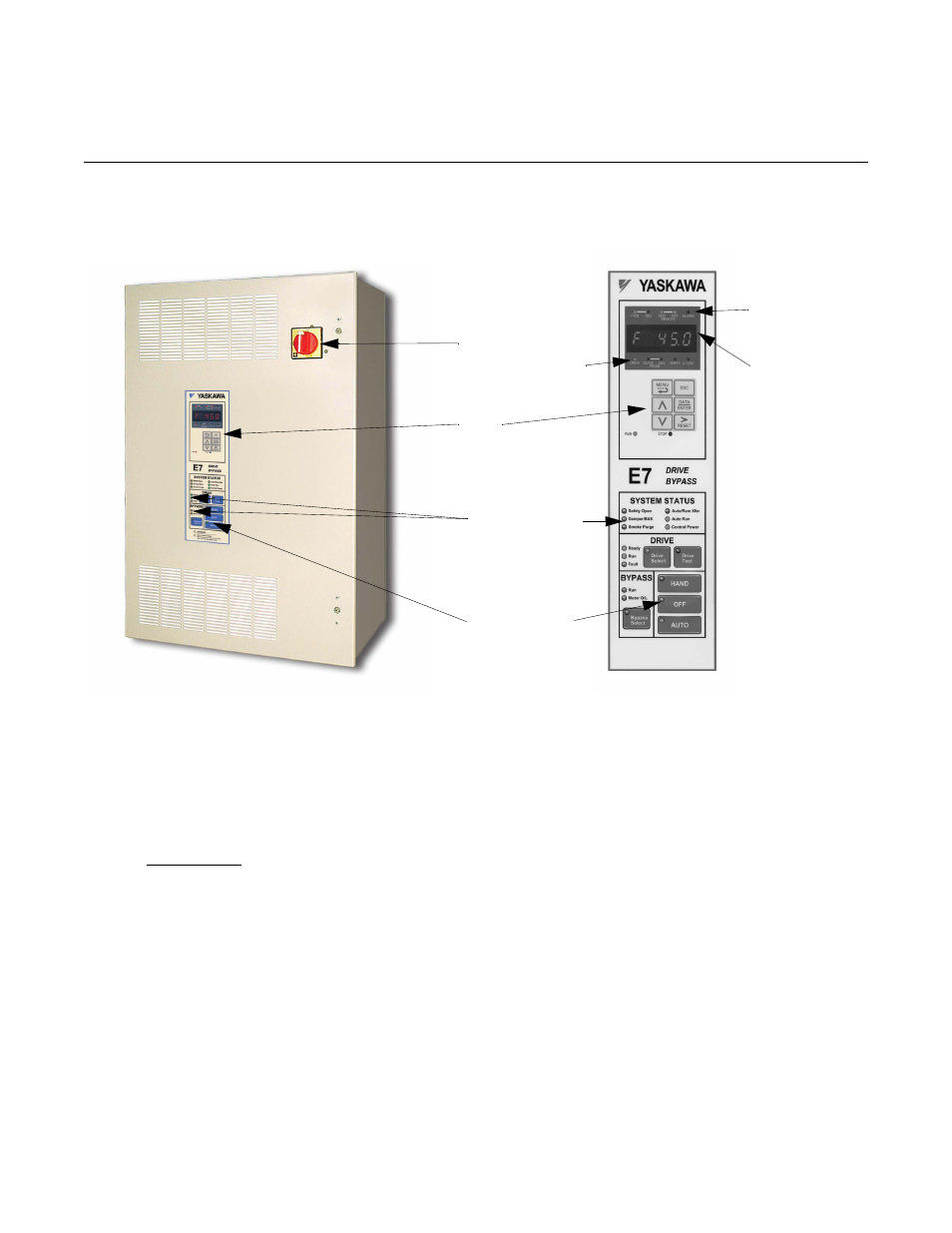
Bypass Unit Front Control Panel
The external appearance, component names, and terminal arrangement of the Bypass unit is shown in Figures 1.4 through 1.8.
Fig 1.4 E7L Bypass Unit Appearance & E7L Control Panel with Keypad Operator Controls
Keypad Control Panel Operator
In a Bypass unit the Drive keypad control panel operator is mounted flush with the hinged door of the enclosure. The Keypad
Control/Operator is equipped with 6 LED illuminated selector keys: Hand, Off, Auto, Drive Select, Bypass Select and Drive
Test. The E7L also features 11 other status LED indicators: Control Power, Drive Ready, Drive Run, Drive Fault, Bypass Run,
Motor O/L, Safety Open, Damper/BAS Interlock, Smoke Purge, Auto Transfer and Auto Run. The membrane over the Drive
keypad is non-removable on these Bypass units (In order to use the keypad copy function on a Bypass unit - order a separate
keypad, part number CDR001115).
The Keypad Control/Operator has a digital alpha/numeric display and keypad, in the upper portion, for Drive operation and
programming. The row of LEDs above the alpha/numeric display indicate Drive operational status. The row of LEDs below
the alpha/numeric display indicate the Drive menu that is presently active.
The lower portion of the Keypad Control/Operator displays the operating mode status via LEDs and controls the HAND/OFF/
AUTO functions for both the Drive and Bypass via a touchpad. The general rule for LED colors, in the lower portion of the
control panel, is:
Green = Normal Status
Amber = Abnormal Status
Red = Fault Status
Drive
Disconnect
Indicating LEDs
H/O/A Keypad
Switch
Keypad
Operator
Drive
Operational
Status
Alpha-Numeric
Menu
Indicating
LEDs
LED Display