Modbus self-diagnosis, Verify that parameter h5-08 = 0 (memobus modbus), Turn off the power supply to the drive – Yaskawa E7L Drive Bypass User Manual
Page 267: Turn on the power supply to the drive again, Communications d - 15
Communications D - 15
Modbus Self-Diagnosis
The Drive has a built-in function for self-diagnosing the operations of serial communication interface circuits. The
self-diagnosis function connects the communication parts of the send and receive terminals, receives the data sent by the
Drive, and checks if communication is being performed normally.
Perform the self-diagnosis function using the following procedure.
1. Turn ON the power supply to the Drive, and set parameter H1-05 (Terminal S7 Function Selection) to 67 (Com Test
Mode).
2. Verify that parameter H5-08 = 0 (Memobus Modbus)
3. Turn OFF the power supply to the Drive.
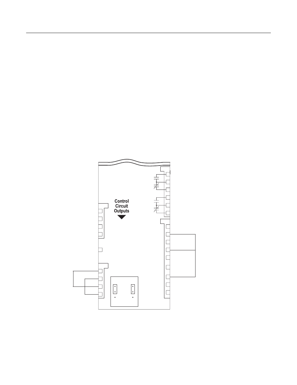
4. Perform wiring according to the following diagram while the power supply is turned OFF.
5. Turn ON the terminating resistance. (Turn ON pin 1 on DIP switch 1.)
6. Turn ON the power supply to the Drive again.
7. During normal self-diagnostic operation, the Digital Operator displays the frequency reference value. If an error occurs, a
CE (Modbus communication error) alarm will be displayed on the Digital Operator, the fault contact output will be turned
ON, and the Drive operation ready signal will be turned OFF.
Fig. D.10 Communication Terminal Connection for Self -Diagnosis Function
1
2
3
4
5
6
4
3
1
2
4
2
3
1
AC
+V
FM
SHIELD
TB2
TB3
CN103
A1/A2 FACTORY SETTING IS 4-20mA CONNECTED TO
DRIVE TERMINAL A2 (AS SELECTED BY DIP SWITCH
S1(2), (3) & (4))
A2
7
8
9
6
5
4
3
2
1
PE
ELECTRONIC BYPASS
CONTROL PCB
S+
S-
R+
R-
AC
AM
+V
(+15VDC, 20mA)
A2
4-20MADC OR 0-10VDC
(AS SELECTED BY
DIP SW. S1(2).
FACTORY SETTING IS
4-20MADC)
TB5
TB4
DRIVE AM MONITOR OUPUT
4-20MADC OR 0-10VDC
(AS SELECTED BY JUMPER J3.
FACTORY SETTING IS 4-20MADC)
PROGRAMMABLE
RELAY #2
PROGRAMMABLE
RELAY #3
(FACTORY SETTING
IS SYSTEM FAULT)
(+15VDC,
20mA)
3
2
4-20
MADC
1
3
2
0-10
VDC
1
J2
J3
(FACTORY SETTING
IS AUTO MODE)
FACTORY SETTINGS
TB3(4)
FM
AM
TB5(6)
DRIVE FM MONITOR OUTPUT
4-20MADC OR 0-10VDC
(AS SELECTED BY JUMPER J2.
FACTORY SETTING IS 4-20MADC)