Drive nameplate information, Fig 1.2 drive nameplate (example), Bypass unit model numbers – Yaskawa E7L Drive Bypass User Manual
Page 19: Fig 1.3 bypass unit model number, Physical installation 1 - 7
Physical Installation 1 - 7
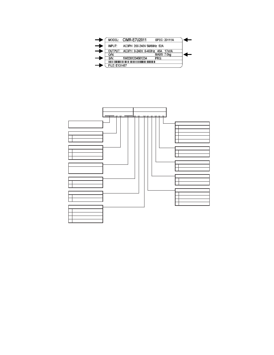
Drive Nameplate Information
A nameplate is also attached to the right side of the Drive inside the Bypass enclosure. The following nameplate is an example
for a standard Drive.
Fig 1.2 Drive Nameplate
(Example)
Bypass Unit Model Numbers
The model number on the nameplate of the Bypass unit indicates the enclosure, voltage, Drive rated current and options of the
Bypass unit in alphanumeric codes.
Fig 1.3 Bypass Unit Model Number
Input Power Specifications
Output Power Specifications
Drive Model Number
Drive Enclosure and
Revision Code
Weight
Serial Number
UL File Number
V B
0 0 G X 0 0 Y L
0
L
V
J
B
0
D
Y
A
B
0
P
0
C
0
0
W
N
0
F
G
H
0
X
Z
R
Enable Metasys N2
3-15 PSI Transducer
Rated Amps (001 - 080)
Current
Voltage
208V
230/240V
480V
E7L 2-Contactor Bypass
Configuration
E 7 L
0 2 1
Enclosure
NEMA 1
NEMA 12
MCP Circuit Breaker
Main Input Disconnect
(Ex.: "021" = 21A)
Disconnect Switch
Drive Keypad
LED Style Keypad
LCD Style Keypad
Drive Input Circuit
3% Bus Reactor
(1)
5% Bus Reactor
(1)
3% Input Reactor
(2)
None
Custom Nameplates
None
None
BASE NUMBER
OPTIONS
None
Communications
Not Enabled
LonWorks
3-15 PSI Transducer
Fu
Disconnect Switch
Fuses & Disc. Switch
ses
Custom Nameplates
Input Filter
None
Cap Filter
Impedance
U
V Enable Modbus
Enable Siemens APOGEE
(1) 3% and 5% Bus Reactors are only available as an option on base numbers up to E7LVA068
and E7LVB040; larger drives have a Bus Reactor as standard
(2) 3% Input Reactor, when combined with the standard Bus Reactor (available on base numbers
E7LVA080 and E7LVB052 and above), yields a total of 5% input impedance