Reference limits, D2-01, Frequency reference upper limit – Yaskawa E7L Drive Bypass User Manual
Page 221: Ref upper limit, 0 to 110.0, Quick setting, D2-02, Frequency reference lower limit, Ref lower limit, D2-03
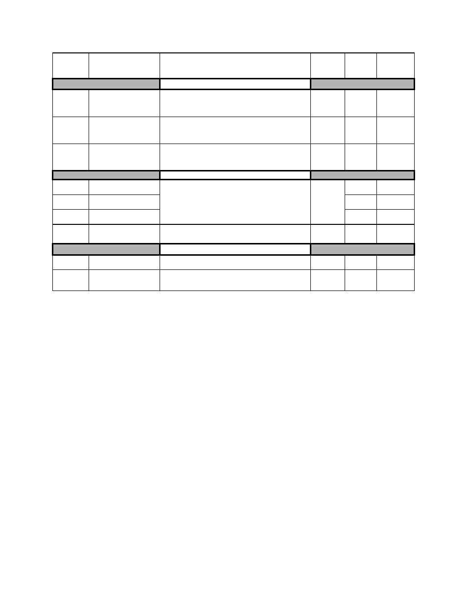
Parameters A - 9
Reference Limits
d2-01
Frequency Reference Upper
Limit
Ref Upper Limit
Determines maximum speed command, set as a percentage of
parameter E1-04. If speed command is above this value, actual
drive speed will be limited to this value. This parameter applies to
all speed command sources.
0.0 to 110.0
100.0%
Quick Setting
d2-02
Frequency Reference Lower
Limit
Ref Lower Limit
Determines minimum speed command, set as a percentage of
parameter E1-04. If speed command is below this value, actual
drive speed will be set to this value. This parameter applies to all
speed command sources.
0.0 to 110.0
0.0%
Quick Setting
d2-03
Master Speed Reference
Lower Limit
Ref1 Lower Limit
Determines the minimum speed command, set as a percentage of
parameter E1-04. If speed command is below this value, actual
drive speed will be set to this value. This parameter only applies to
analog inputs A1 and A2.
0.0 to 110.0
0.0%
Programming
Jump Frequencies
d3-01
Jump Frequency 1
Jump Freq 1
These parameters allow programming of up to three prohibited
frequency points for eliminating problems with resonant vibration
of the motor / machine. This feature does not actually eliminate the
selected frequency values, but will accelerate and decelerate the
motor through the prohibited bandwidth.
0.0 to 200.0
0.0Hz
Programming
d3-02
Jump Frequency 2
Jump Freq 2
0.0Hz
Programming
d3-03
Jump Frequency 3
Jump Freq 3
0.0Hz
Programming
d3-04
Jump Frequency Width
Jump Bandwidth
This parameter determines the width of the deadband around each
selected prohibited frequency point. A setting of "1.0" will result
in a deadband of +/- 1.0 Hz.
0.0 to 20.0
1.0Hz
Programming
MOP and Trim Control
d4-01
MOP Ref Memory
0: Disabled
1: Enabled
0 or 1
0
Programming
d4-02
Trim Control Level
Trim Control Lvl
Set the percentage of maximum speed to be added or subtracted via
multi-function inputs.
0 to 100
10%
Programming
Table A.1 Parameter List (Continued)
Parameter
No.
Parameter Name
LCD Digital Operator
Display
Description
Setting
Range
Factory
Setting
Menu
Location