Bypass unit basic programming parameters, Programming 5 - 4 – Yaskawa E7L Drive Bypass User Manual
Page 96

Programming 5 - 4
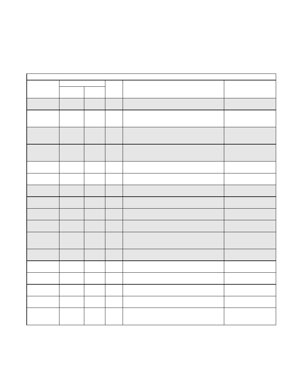
Bypass Unit Basic Programming Parameters
The basic Drive programming for a Bypass unit is different from that of a Drive installation without the Bypass option.
Several Drive parameters have been programmed at the factory to meet the needs of the Bypass logic circuit. See Table 5.1
below, the highlighted parameters are required by the Bypass logic circuit. Only those parameters that are changed from the
Drive default are listed.
Table 5.1 Bypass Parameter Settings
PARAMETER
NUMBER
SETTING
UNITS
DESCRIPTION
OPTIONAL LCD
KEYPAD DISPLAY
For Bypass Setting
For Bypass
Drive
Default
b1-01
SEE
TABLE 5.2
1
N/A
Frequency Reference Selection – Selects the speed
command input source
Reference Source /
Terminals
b1-08
1
0
N/A
Run Command Selection During Programming –
Selects if run command is accepted in DRIVE Opera-
tion menu only or in all menus.
RUN CMD at PRG /
Enabled
d1-01
10.0
0.0
HZ
Frequency Reference 1 – Hand Mode Speed Reference,
used with serial communication, see Table 5.2 and
H1-03
Reference 1 / (0-60)
d1-02
6.0
0.0
HZ
Frequency Reference 2 – Hand Mode Speed Reference,
used without serial communication, see Table 5.2 and
H1-03
Reference 2 / (0-60)
E1-01
208, 240 or
480
240 or
480
VOLTS Input Voltage Setting – Set to the nominal Voltage Set-
ting for the incoming line
Input Voltage / (range)
E1-05
208, 230 or
460
208, 240
or 480
VOLTS Output Volts Setting – Set to the nominal Voltage Rat-
ing of motors
Output Voltage / (range)
H1-01
70
24
N/A
Drive Terminal S3 Function Selection – Set for Drive
run enable
Terminal S3 Sel / Drive
Enable
H1-02
SEE
TABLE 5.2
14
N/A
Drive Terminal S4 Function Selection – Set for fault
reset or Frequency Reference 1
Terminal S4 Sel / Multi-
Step Ref 1
H1-03
SEE
TABLE 5.2
3
N/A
Drive Terminal S5 Function Selection – Set For Fre-
quency Reference 1 or Serial Communication
Terminal S5 Sel / Multi-
Step Ref 1
H2-02
3B
A
N/A
Drive Terminals M3 - M4 Function Selection – Set for
serial communication run command
Term M3-M4 Sel / Com
RUN Command
H3-08
SEE
TABLE 5.2
2
N/A
Drive Terminal A2 Signal Level –Signal selection, 0 to
10 VDC (Drive control board switch S1-2 off) or 4 to
20 mA (Drive control board switch S1-2 on)
Term A2 Signal / 0-10
VDC
H3-09
SEE
TABLE 5.2
2
N/A
Drive Terminal A2 Function Selection – Selects how
this input will be used by the Drive
Terminal A2 Sel / Aux Ref-
erence
H5-02
SEE
TABLE 5.2
3
N/A
Serial Communication Speed Selection, Baud Rate
Serial Baud Rate 1
9600 Baud
H5-07
SEE
TABLE 5.2
1
N/A
Serial Communication Request to Send Control
RT5 Control Sel/enabled
H5-08
SEE
TABLE 5.2
0
N/A
Serial Communication Protocol Selection
Protocol Select/N2
(Metasys)
H5-09
10.0
2
SEC
Serial Communication Error Detection Time
CE Detect Time/
(0.0 - 10.0)
L4-05
0
1
N/A
Frequency Reference Loss Detection Selection – Deter-
mines Drive response to loss of the frequency speed
command
Ref Loss Sel / Stop