Adjusting arcglide parameters with the hmi, Formation, see, Adjusting – Hypertherm THC ArcGlide User Manual
Page 283
ArcGlide THC Instruction Manual 806450
283
B – ArcGlide THC Serial Communication Installation
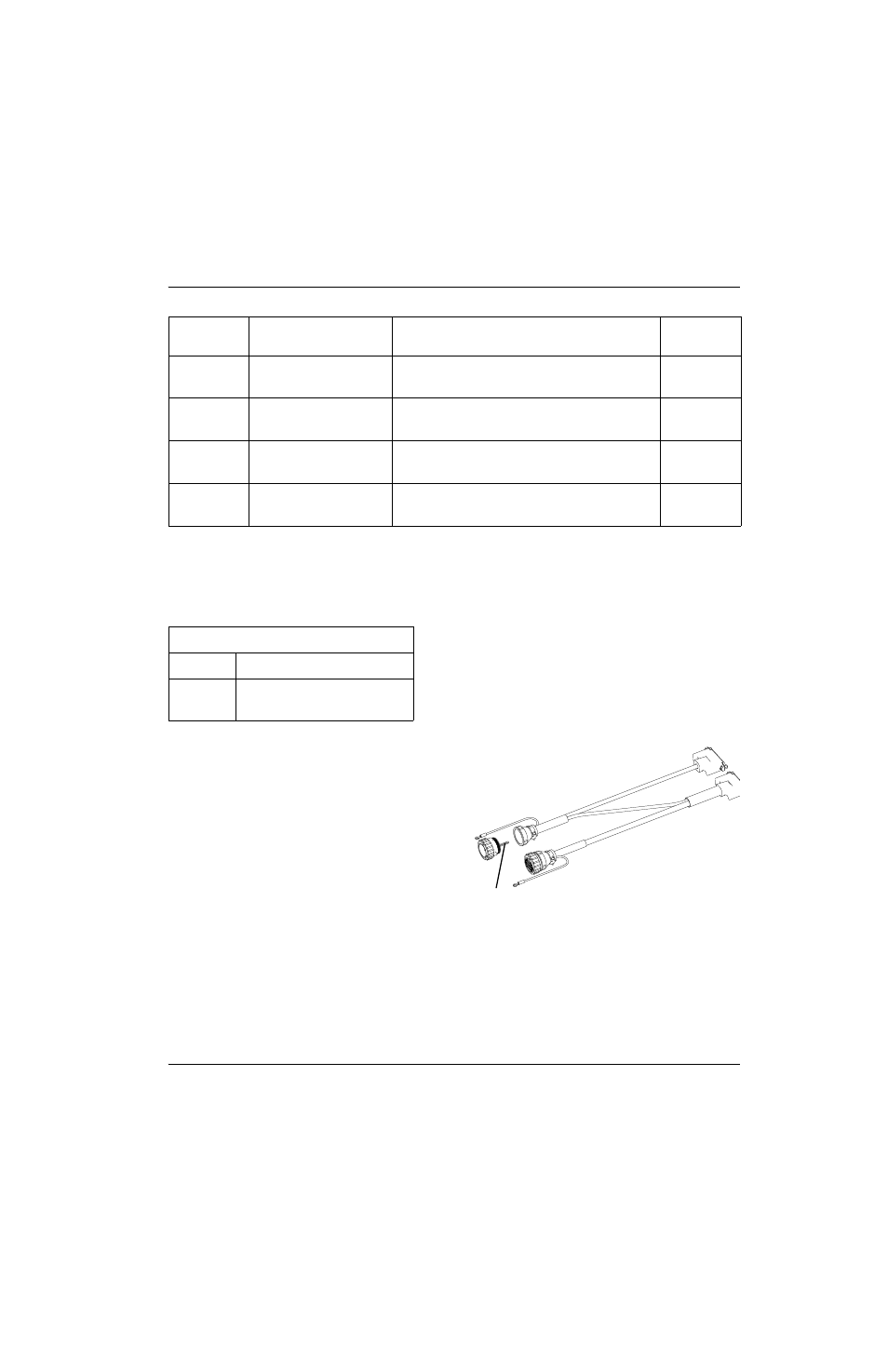
Adjusting ArcGlide parameters with the HMI
The jumper on pins 14 and 15 in Connector A limit the HMI to monitoring ArcGlide functions. To enable the HMI to adjust
ArcGlide parameters, you must remove pins 14 and 15 and the jumper wire from Connector A, using a contact extraction
tool (008197).
To remove the jumper in Connector A:
1. Remove the 2 screws from the cable clamp around the
connector.
2. Unscrew the backshell from the connector.
3. Insert the contact extraction tool into pin position 14 and
push the end of the tool to remove the pin.
4. Repeat Step 3 for pin position 15.
5. Pull the jumper wire from the back of the connector.
6. Screw the backshell onto the connector.
7. Replace the cable clamp around the connector and fasten the 2 screws.
19
20
Green
Red
THC Error output A
THC Error output B
33
14
23
24
Blue
Red
CNC Spare output A
CNC Spare output B
30
11
25
26
Yellow
Red
Interlock input +
Interlock input -
35
16
29
34
Brown
Red
Field common
Field 23 V
18
37
Jumper wire in Connector A:
Pin No.
Signal
14
15
Serial enable +
Input common -
Connector B
Pin No.
Wire color
Signal
Connector D
Pin No.
Jumper wire