Hypertherm THC ArcGlide User Manual
Page 71
ArcGlide THC Instruction Manual 806450
71
2 – Installation
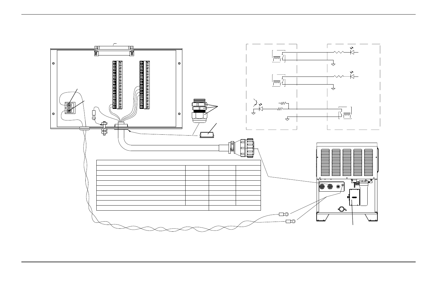
9 – Discrete plasma interface board with connection to MAX200, HT2000, or HT2000 LHF plasma system
1
2
7
8
6
5
IHS SYNC
J3-5
J3-6
HOLD
1
RELAY
RELAY
PLASMA START
PULL UP
24V
J2-2
FIELD COMMON
J2-1
J3-8
J3-7
HOLD IGNITION
MACHINE MOTION
DELAYED
36(37)
31(32)
9
START
15
5
J2
J3
COMMON
COMMON
1X6
MACHINE
( ) - FOR HT2000, HT2000LHF
+24V
+24V
Plasma interface board (141094), mounted externally
by the customer
Discrete plasma interface board
(141094)
1 x 6 machine interface cable
Remove
Replace with
bushing (008245)
Electrode -
Work +
Motion - Red
Hold A - White
Start B - Black
Hold B- Black
Common - Blue
Not connected
Plasma interface termination
Signal
Wire color
Pin
Cable label
Plasma Start A
Blue
9
82
Plasma Start B
Black
15
83
Hold A
White
1
87
Hold B
Black
5
86
Motion
Red
36 (37*)
84
Common
Blue
31 (32*)
85
Ring terminal to ground stud
Shield wire
No connection
Set plasma inputs to dry (D) using the input switch on the control module.
( * ) For HT2000, HT2000LHF
ArcGlide plasma interface terminal blocks
Machine interface 1 X 6 CPC connector
To plasma system
Work +
To plasma system
Electrode -
Refer to the
HT2000 Instruction
Manual (802070) or the
HT2000LHF Instruction Manual
(803020) for information about the
1 X 6 connection
Arc voltage sense wires to plasma system, use ~0.9 mm
2
(18 AWG) twisted pair wire,
rated 600 V or greater.
Start A - Blue