Hypertherm THC ArcGlide User Manual
Page 72
72
ArcGlide THC Instruction Manual 806450
2 – Installation
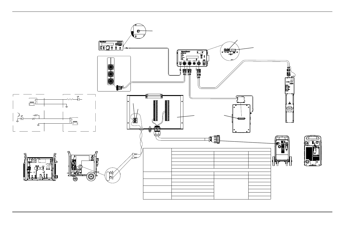
10 – Discrete plasma interface board with connection to Powermax plasma systems
1
2
7
8
RELAY
PLASMA START
PULL UP
24V
J2-2
FIELD COMMON
J2-1
J3-8
J3-7
MACHINE MOTION
12
14
3
START
4
J2
J3
COMMON
J6
J5
J3
J2
J1
J27
WORK
LEAD
J26
RED
J18
ORG
J17
J11
B
R
J28
J15
J16
+24V
Optional ArcGlide HMI
Motion - Red
CNC with Picopath interface
Start - Green
Start - Black
Common -
Black
Powermax machine interface
connector
Terminal blocks on the
discrete plasma interface
board
For Work and Electrode connections, see the table at right.
Powermax
65/85/105/125
Powermax
1000/1230/1650
Plasma Interface Termination
Signal
Wire color
Powermax pins
Plasma Start A
Green
3
Plasma Start B
Black
4
Motion A
Red
12
Common
Black
14
Arc voltage
1000/1230/1650
Electrode-
0.9 mm
2
(18 AWG)
J16
Work+
0.9 mm
2
(18 AWG)
J15
65/85 CSA
Electrode-
0.9 mm
2
(18 AWG)
See Field Service Bulletin
Machine Interface for
Raw Arc Voltage
(807060)
J28
Work+
J26
65/85 CE
Electrode-
J29
Work+
J27
105/125 CSA or CE Electrode-
J28
Work+
J27
ArcGlide control module
CNC I/O cable
Shielded Ethernet cable
Rotary address switch, set to 1
Rotary address switch, set to 1
Set ArcGlide plasma inputs to dry (D) using the plasma input
switch on the THC processor board in the control module.
Lifter I/O cable
Plasma I/O cable
Discrete plasma interface
board (141094)
ArcGlide lifter
Powermax
1000/1230/1650
Powermax
65/85/105/125
Powermax machine interface cable
(023206)
Electrode -
Work +
Arc voltage sense wires to plasma system.
Use ~0.9 mm
2
(18 AWG) twisted pair wire,
rated 600 V or greater.
Axes 1, 2
I/O
Axes 3, 4