Configuring ospf dr election, Network requirements, Network diagram – H3C Technologies H3C WX6000 Series Access Controllers User Manual
Page 278: Configuration procedure
25-44
Intra Area: 2 Inter Area: 3 ASE: 1 NSSA: 0
You can see on Switch C an external route imported from the NSSA area.
Configuring OSPF DR Election
Network requirements
z
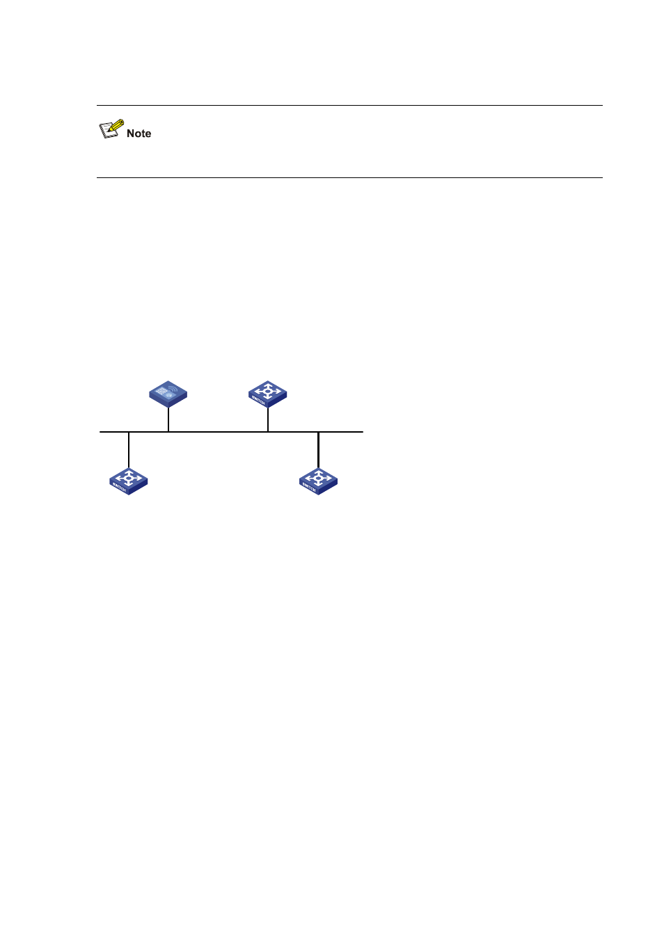
In the following figure, AC, Switches A, B and C run OSPF and reside on the same network
segment.
z
It is required to configure AC as the DR, and configure Switch B as the BDR.
Network diagram
Figure 25-24
Network diagram for OSPF DR election configuration
AC
Switch A
Switch B
Switch C
Vlan-int 100
196.1.1.1/24
Vlan-int 100
196.1.1.2/24
Vlan-int 100
196.1.1.4/24
Vlan-int 100
196.1.1.3/24
DR
BDR
Configuration procedure
1) Configure IP addresses for interfaces (omitted)
2) Configure OSPF basic functions
# Configure AC.
<AC> system-view
[AC] router id 1.1.1.1
[AC] ospf
[AC-ospf-1] area 0
[AC-ospf-1-area-0.0.0.0] network 196.1.1.0 0.0.0.255
[AC-ospf-1-area-0.0.0.0] quit
[AC-ospf-1] quit
# Configure Switch A.
<SwitchA> system-view
[SwitchA] router id 2.2.2.2
[SwitchA] ospf
[SwitchA-ospf-1] area 0
[SwitchA-ospf-1-area-0.0.0.0] network 196.1.1.0 0.0.0.255
[SwitchA-ospf-1-area-0.0.0.0] quit
[SwitchA-ospf-1] quit