Configuring ospf virtual links, Network requirements, Network diagram – H3C Technologies H3C WX6000 Series Access Controllers User Manual
Page 282: Configuration procedure
25-48
Area: 0.0.0.0
IP Address Type State Cost Pri DR BDR
192.168.1.2 Broadcast DROther 1 0 192.168.1.1 192.168.1.3
The interface state DROther means the interface is not the DR/BDR.
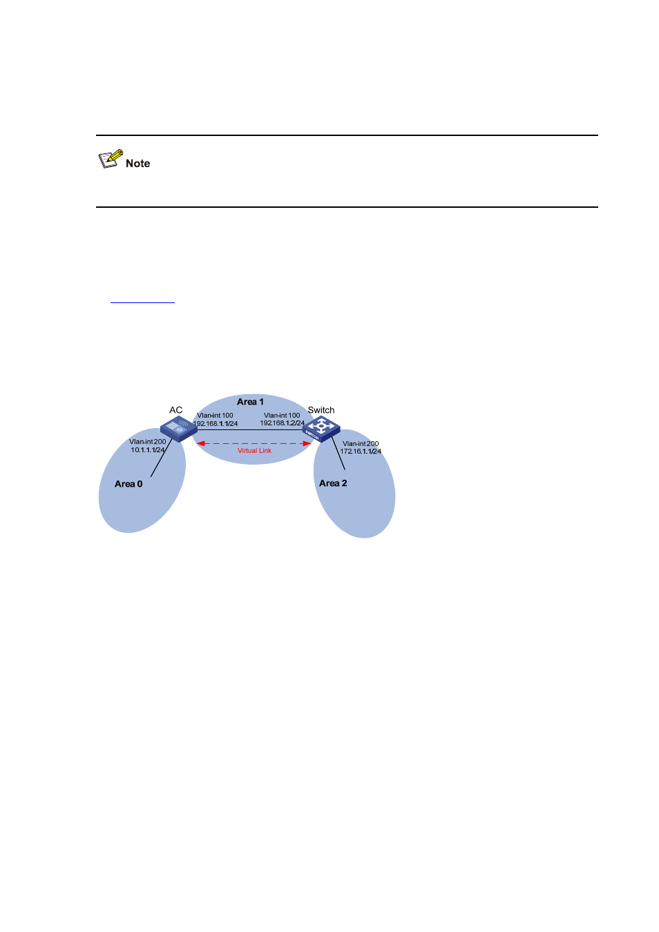
Configuring OSPF Virtual Links
Network requirements
In
, Area 2 has no direct connection to Area 0, and Area 1 acts as the Transit Area to
connect Area 2 to Area 0 via a configured virtual link between AC and Switch.
After configuration, AC can learn routes to Area 2.
Network diagram
Figure 25-25
Network diagram for OSPF virtual link configuration
Configuration procedure
1) Configure IP addresses for interfaces (omitted)
2) Configure OSPF basic functions
# Configure AC.
<AC> system-view
[AC] ospf 1 router-id 1.1.1.1
[AC-ospf-1] area 0
[AC-ospf-1-area-0.0.0.0] network 10.0.0.0 0.255.255.255
[AC-ospf-1-area-0.0.0.0] quit
[AC-ospf-1] area 1
[AC-ospf-1-area-0.0.0.1] network 192.168.1.0 0.0.0.255
[AC-ospf-1-area-0.0.0.1] quit
# Configure Switch.
<Switch> system-view
[Switch] ospf 1 router-id 2.2.2.2
[Switch-ospf-1] area 1
[Switch-ospf-1-area-0.0.0.1] network 192.168.1.0 0.0.0.255
[Switch-ospf-1-area-0.0.0.1] quit