Network diagram, Configuration procedure – H3C Technologies H3C WX6000 Series Access Controllers User Manual
Page 509
54-24
Network diagram
Figure 54-12
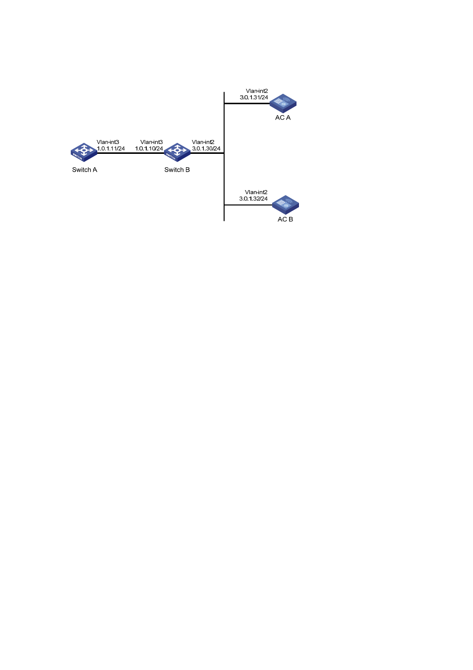
Network diagram for configuration of NTP broadcast mode with authentication
Configuration procedure
1) Configuration on AC A:
# Specify the local clock as the reference source, with the stratum level of 3.
<AC A> system-view
[AC A] ntp-service refclock-master 3
# Configure NTP authentication
[AC A] ntp-service authentication enable
[AC A] ntp-service authentication-keyid 88 authentication-mode md5 123456
[AC A] ntp-service reliable authentication-keyid 88
# Specify AC A as an NTP broadcast server, and specify an authentication key.
[AC A] interface vlan-interface 2
[AC A-Vlan-interface2] ntp-service broadcast-server authentication-keyid 88
2) Configuration on AC B:
# Configure NTP authentication
<AC B> system-view
[AC B] ntp-service authentication enable
[AC B] ntp-service authentication-keyid 88 authentication-mode md5 123456
[AC B] ntp-service reliable authentication-keyid 88
# Configure AC B to work in the NTP broadcast client mode
[AC B] interface vlan-interface 2
[AC B-Vlan-interface2] ntp-service broadcast-client
Now, AC B can listen to the broadcast messages through VLAN-interface 2, and AC A can send
broadcast messages through VLAN-interface 2. Upon receiving a broadcast message from AC A, AC B
synchronizes its clock to that of AC A.
# View the NTP status of AC B after clock synchronization.
[AC B-Vlan-interface2] display ntp-service status
Clock status: synchronized
Clock stratum: 4
Reference clock ID: 3.0.1.31
Nominal frequency: 100.0000 Hz
Actual frequency: 100.0000 Hz