Snmp logging configuration example, Network requirements, Network diagram – H3C Technologies H3C WX6000 Series Access Controllers User Manual
Page 477
52-9
[Sysname] snmp-agent community write private
# Configure VLAN-interface 2 (with the IP address of 1.1.1.1/24). Add the port GigabitEthernet 0/0//1 to
VLAN 2.
[Sysname] vlan 2
[Sysname-vlan2] port GigabitEthernet 0/0/1
[Sysname-vlan2] interface vlan-interface 2
[Sysname-Vlan-interface2] ip address 1.1.1.1 255.255.255.0
[Sysname-Vlan-interface2] quit
# Configure the contact person and physical location information of the access controller.
[Sysname] snmp-agent sys-info contact Mr.Wang-Tel:3306
[Sysname] snmp-agent sys-info location telephone-closet,3rd-floor
# Enable the sending of Traps to the NMS with an IP address of 1.1.1.2/24, using public as the
community name.
[Sysname] snmp-agent trap enable
[Sysname] snmp-agent target-host trap address udp-domain 1.1.1.2 udp-port 5000 params
securityname public
2) Configuring SNMP NMS
With SNMPv2c, the user needs to specify the read only community, the read and write community, the
timeout time, and number of retries. The user can inquire and configure the device through the NMS.
The configurations on the agent and the NMS must match.
SNMP Logging Configuration Example
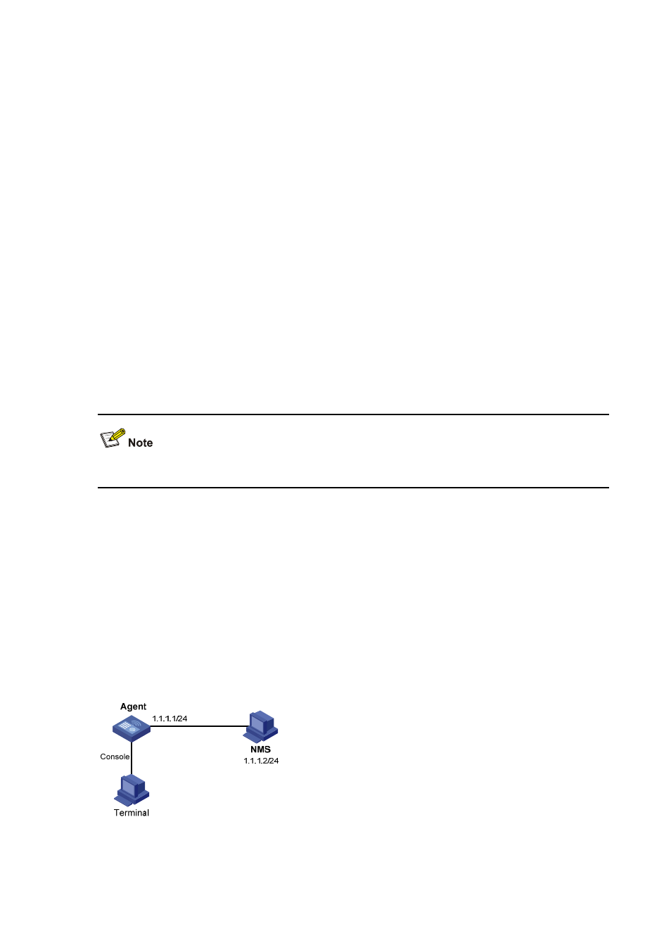
Network requirements
z
NMS and Agent are connected through an Ethernet
z
The IP address of NMS is 1.1.1.2/24
z
The IP address of the VLAN interface on Agent is 1.1.1.1/24
z
Configure community name, access right and SNMP version on Agent
Network diagram
Figure 52-4
Network diagram for SNMP logging