Introduction to system debugging – H3C Technologies H3C WX6000 Series Access Controllers User Manual
Page 573
61-2
3) The source device sends a packet with a TTL value of 2 to the destination device.
4) The second hop responds with a TTL-expired ICMP message, which gives the source device the
address of the second router.
5) The above process continues until the ultimate destination device is reached. In this way, the
source device can trace the addresses of all the routers that have been used to get to the
destination device.
Introduction to System Debugging
The device provides various debugging functions. For the majority of protocols and features supported,
the system provides corresponding debugging information to help users diagnose errors.
The following two switches control the display of debugging information:
z
Protocol debugging switch, which controls protocol-specific debugging information
z
Screen output switch, which controls whether to display the debugging information on a certain
screen.
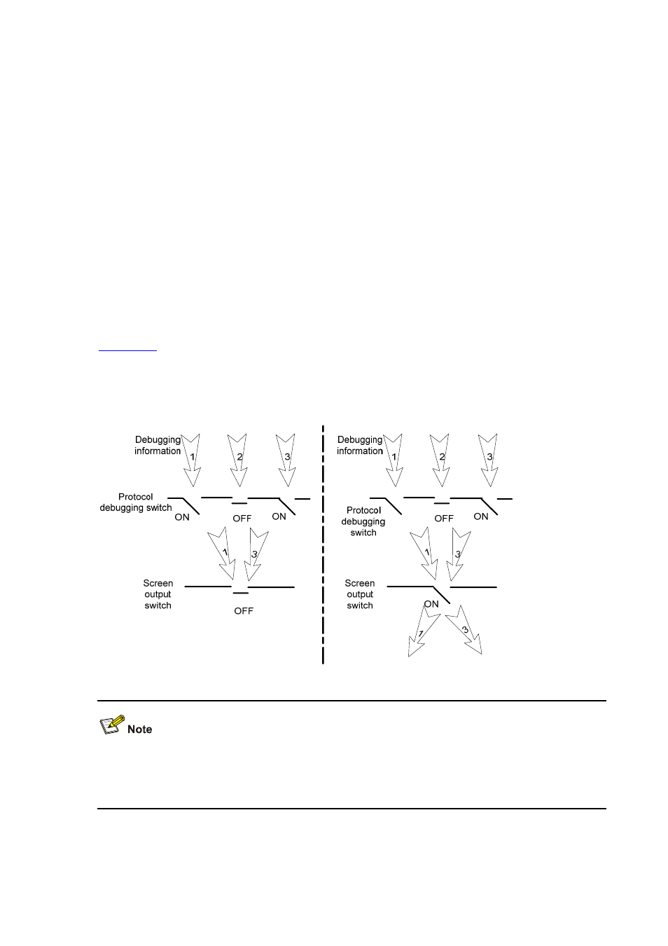
illustrates the relationship between the protocol debugging switch and the screen output
switch. Assume that the device can output debugging information to module 1, 2 and 3. Only when both
are turned on can debugging information be output on a terminal.
Figure 61-1
The relationship between the protocol and screen debugging switch
Displaying debugging information on the terminal is the most commonly used way to output debugging
information. You can also output debugging information to other directions. For details, refer to
Information Center
in H3C WX6103 Access Controller Switch Interface Board Configuration Guide.