Sflow configuration example, Network requirements, Network diagram – H3C Technologies H3C WX6000 Series Access Controllers User Manual
Page 361: Configuration procedure
32-3
sFlow Configuration Example
Network requirements
z
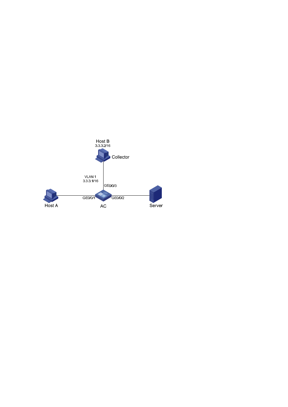
Host A and Server are connected to AC through GigabitEthernet 0/0/1 and GigabitEthernet 0/0/2
respectively.
z
Host B works as an sFlow collector with IP address 3.3.3.2 and port number 6343, and is
connected to AC through GigabitEthernet 0/0/3.
z
GigabitEthernet 0/0/3 belongs to VLAN 1, having an IP address of 3.3.3.1.
Run sFlow agent on AC, and enable sFlow on GigabitEthernet 0/0/1 to monitor traffic on this interface.
AC sends sFlow packets through GigabitEthernet 0/0/3 to Host B, which then analyzes the sFlow
packets and displays the results.
Network diagram
Figure 32-1
Network diagram for sFlow configuration
Configuration procedure
# Configure an IP address for the sFlow agent.
<AC> system-view
[AC] sflow agent ip 3.3.3.1
# Specify the IP address and port number of the sFlow collector.
[AC] sflow collector ip 3.3.3.2
# Set the sFlow interval to 30 seconds.
[AC] sflow interval 30
# Enable sFlow in both the inbound and outbound directions on GigabitEthernet 0/0/1.
[AC] interface GigabitEthernet 0/0/1
[AC-GigabitEthernet0/0/1] sflow enable both
# Specify the traffic sampling rate.
[AC-GigabitEthernet0/0/1] sflow sampling-rate 100000
# Display the sFlow configuration information.
[AC-GigabitEthernet0/0/1] display sflow
sFlow Global Information:
Agent IP:3.3.3.1
Collector IP:3.3.3.2 Port: 6343
Interval(s): 30
sFlow Port Information:
Interface Direction Rate Mode Status