Network requirements, Upgrade procedure – H3C Technologies H3C S12500 Series Switches User Manual
Page 134
122
<Device>
# Specify the main startup system software image on the active MPU.
<Device> boot-loader file soft-version2.bin slot 0 main
# Copy the image from the active MPU to the standby MPU.
<Device> copy soft-version2.bin slot1#flash:/soft-version2.bin
# Specify the image as the main startup system software image on the standby MPU.
<Device> boot-loader file slot1#flash:/soft-version2.bin slot 1 main
# Reboot the device to complete the upgrade.
<Device> reboot
3.
Use the display version command to verify the upgrade.
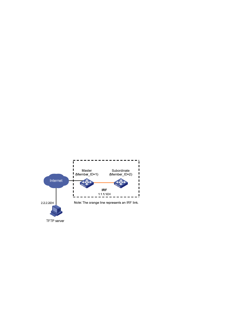
System software image upgrade example (in IRF mode)
Network requirements
has two member switches: the master with the member ID 1 and the
subordinate switch with the member ID 2. Each member has an active MPU in slot 0 and a standby MPU
in slot 1. The current software version is soft-version1 for the IRF fabric. The latest application
soft-version2.bin and the latest configuration file new-config.cfg are both saved on the TFTP server. The
TFTP server and the IRF fabric can reach each other.
Upgrade the software version of the IRF fabric to soft-version2 and configuration file to new-config.
Figure 41 Network diagram
Upgrade procedure
1.
Configure the TFTP server. (Details not shown.)
2.
Configure the IRF member switches:
# Download new-config.cfg from the TFTP server to the active MPU of the master.
<IRF> tftp 2.2.2.2 get new-config.cfg
..
File will be transferred in binary mode
Downloading file from remote TFTP server, please wait.....
TFTP: 917 bytes received in 1 second(s)
File downloaded successfully.
<IRF> copy new-config.cfg chassis1#slot1#flash:/new-config.cfg