Configuration procedure – H3C Technologies H3C S12500 Series Switches User Manual
Page 71
59
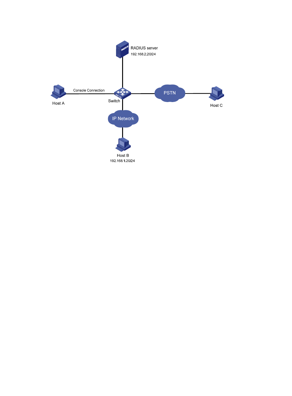
Figure 22 Network diagram
Configuration procedure
# Assign IP addresses to the interfaces on the switch so that the switch and Host B can reach each other
and the switch and the RADIUS server can reach each other. (Details not shown.)
# Enable the Telnet service on the switch.
<Sysname> system-view
[Sysname] telnet server enable
# Configure the switch to perform no authentication for users logging in through the console port and to
allow the users to use commands of privilege level 3 (all commands).
[Sysname] user-interface console 0
[Sysname-ui-console0] authentication-mode none
[Sysname-ui-console0] user privilege level 3
[Sysname-ui-console0] quit
# Configure the switch to perform password authentication for users logging in to VTY user interfaces 0
through 4. Set the password to 123, and set the privilege level of the users to 2.
[Sysname] user-interface vty 0 4
[Sysname-ui-vty0-4] authentication-mode password
[Sysname-ui-vty0-4] set authentication password cipher 123
[Sysname-ui-vty0-4] user privilege level 2
[Sysname-ui-vty0-4] quit
# Configure the switch to use AAA to authenticate users logging in to user interface VTY 5.
[Sysname] user-interface vty 5
[Sysname-ui-vty5] authentication-mode scheme
[Sysname-ui-vty5] quit
# Create a RADIUS scheme and configure the IP address and UDP port for the primary authentication
server for the scheme. Make sure that the port number is consistent with that on the RADIUS server. Set
the shared key for authentication packets to expert for the scheme and the RADIUS server type of the