NewTek TriCaster 855 User Manual
Page 43
Page | 27
Figure 16
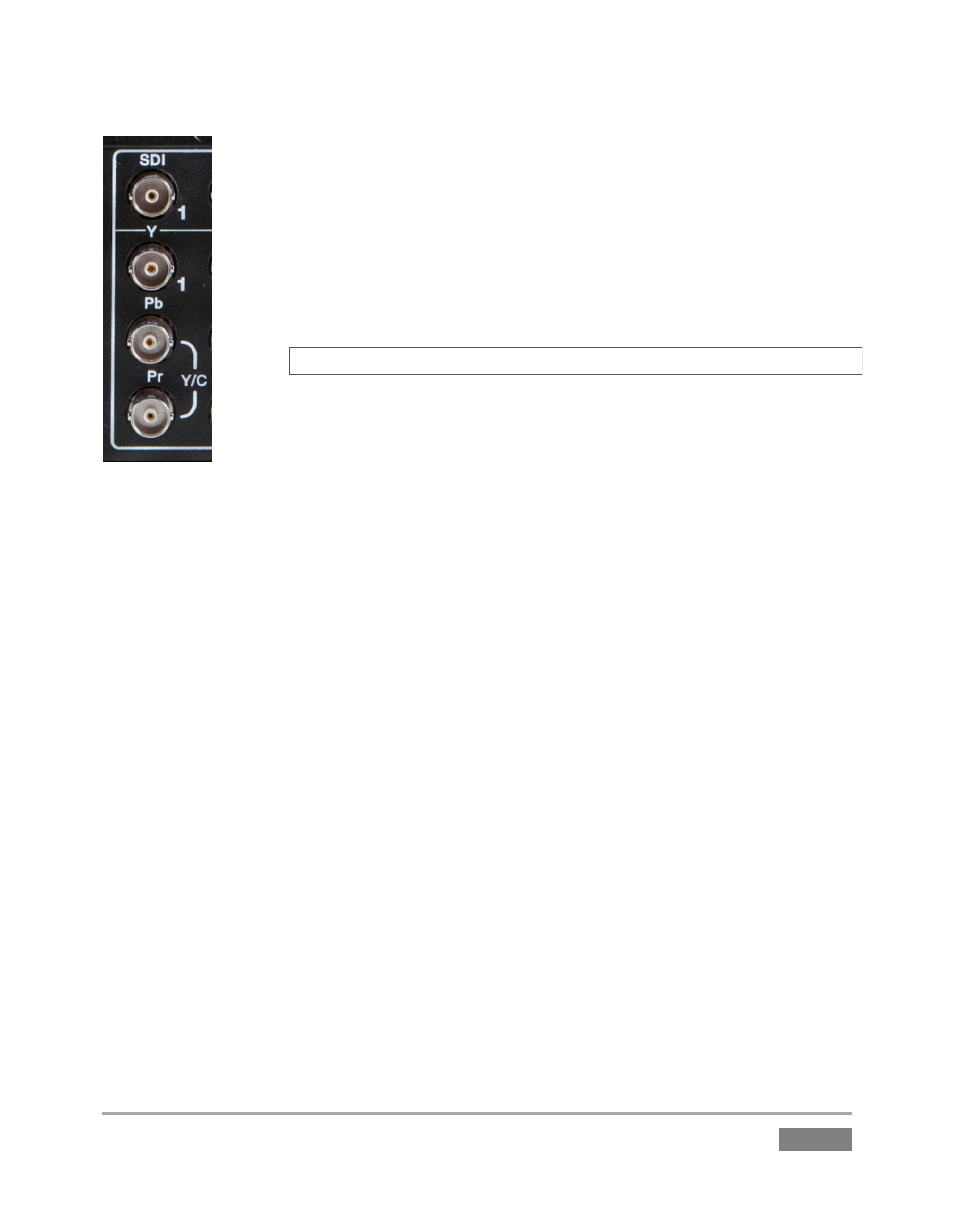
1. Connect downstream video devices to the appropriate output connectors in
the VIDEO OUT section, whether SDI, Component, Y/C (BNC) or Composite.
Please note that the latter two formats may require RCA (cinch plug) or S-
video (4 pin mini-DIN) to BNC adapters, and also that both of these
connection options support output at SD resolution only.
a. SDI
–
Attach SDI connectors to the uppermost row of BNC
connectors in the VIDEO OUT group, labeled 1, 2 and AUX.
Hint: If your equipment supports SDI, this is your best quality option.
b. Component – Attach your device to the second, third and fourth
BNC connectors (Y, Pb and Pr).
c. Y/C
–
If your S-Video equipment and cabling has the usual 4-pin mini-DIN
connectors, you will need an ‘S-Video to dual BNC’ adapter. Attach the Y (luma)
connector of your device to the second analog BNC connector row (labeled Pb at far
left in the VIDEO IN group). Attach the C (chroma) connector to the third analog
connector (labeled Pr).
d. Composite – Attach the device’s connector to the first (top) analog connector,
labeled Y.
2. Connect TriCaster’s audio outputs:
a. Analog audio – Connect external audio devices to the connectors in the AUDIO
OUT section.
Note that there are two pairs of two connectors each; Connectors 1a and 1b
provide Program (Master) output, while 2a and 2b are designated AUX
(Auxiliary Output). These two output sections are configured and controlled
separately in the Live Desktop.
b. Digital audio – A separate digital audio connection is not necessary for SDI
output with embedded audio.