Confi gure > protocol switch 4.66 – Westermo MR Series User Manual
Page 207
207
6622-3201
Web Interface and Command Line Reference Guide
www.westermo.com
Confi gure > Protocol Switch
4.66
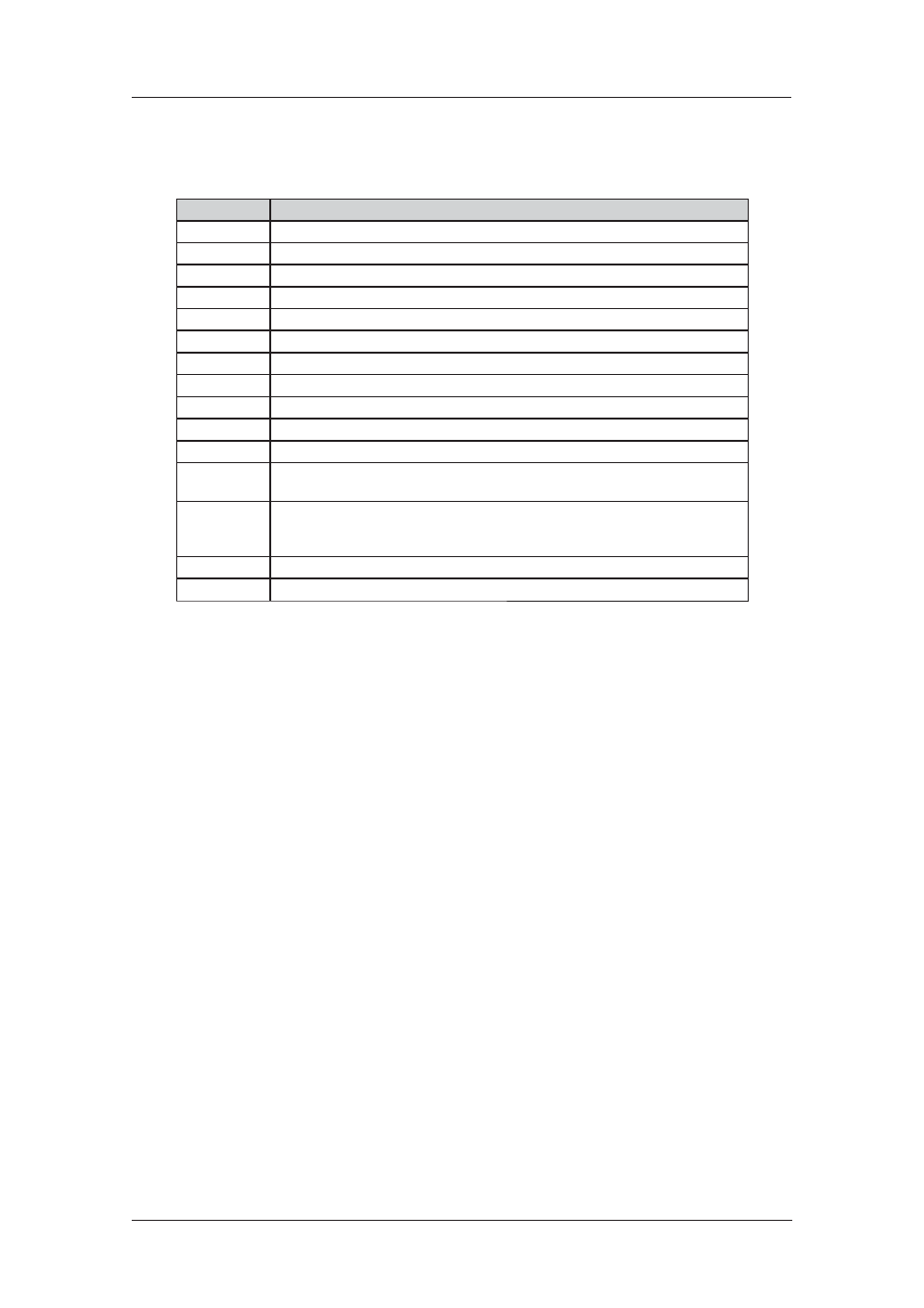
The Protocol Switch software available on some models provides X.25 call switching between the
var ious interfaces that may be available including:
Interface
Description
Off/None
Data will not be switched from / backed-up from this protocol
LAPD
Data will be switched from / backed-up from LAPD using the X.25 service.
LAPD X
As above but the actual LAPD instance used will be determined by the NUA.
LAPB 0
Data will be switched from / backed-up from LAPB 0.
LAPB 1
Data will be switched from / backed-up from LAPB 1.
LAPB 2
Data will be switched from / backed-up from LAPB 2.
LAPB 0 PVC
Data will be switched from / backed-up from an X.25 PVC on LAPB 0.
LAPB 1 PVC
Data will be switched from / backed-up from an X.25 PVC on LAPB 1.
LAPB 2 PVC
Data will be switched from / backed-up from an X.25 PVC on LAPB 2.
XOT
Data will be switched from / backed-up from an XOT (X.25 over TCP/IP) connection.
XOT PVC
Data will be switched from / backed-up from an XOT PVC connection.
TCP stream
Data will be switched from / backed-up from a TCP socket. The socket’s IP address will be
deter mined from the IP stream port setting.
UDP stream
This is similar to the TCP stream setting but instead of switching onto a TCP socket, data is
switched onto a UDP socket. The effect is that a UDP frame will be sent for each packet of
X.25 data being switched.
VXN
Data will be backed-up from Datawire’s VXN protocol
SSL
Data will be switched from / backed-up from SSL
When this optional feature is included, the unit may be configured to pass X.25 calls received via
one of these interfaces to another interface. In addition, it is possible to specify a backup interface
so that if an outgoing call on one interface fails, then the backup interface is automatically tried. The
physical interfaces used by the LAPB instances are specified in the appropriate Configure > LAPB
pages, and may either be ISDN or one of SYN 0 or SYN 1 operating in synchronous mode on a
physical port.
The logic used in the switching software is outlined in the flowchart below. The following notes pro-
vide a more in-depth explanation of the actions taken in each of the numbered boxes.
The unit will first look up the Called NUA/NUI in the Configure > X25 > NUA/NUI–>Interface
mapping table to determine the IP address to use in the event that the call ends up being switched
to a TCP or XOT interface. If a match is found on the Called NUA/NUI the unit assigns the match-
ing IP address from the table to the call. If IP address mapping table does not contain an entry for
the Called NUA/NUI and the call is eventually switched to a TCP or XOT channel then the default
IP address (XOT remote IP address) is used.
The unit then determines from the source interface of the incoming call which interface type it
should be switched to (from the Switch from parameters on the Configure > Protocol Switch
page). For example, if the call arrived via a LAPB 0 interface and the Switch from LAPB 0 to param-
eter was set to LAPD, then the outgoing interface would LAPD.
If the outgoing interface is LAPD the unit changes the Calling NUA field of the incoming call to
the D-Channel NUA value (as defined on the Configure > Protocol Switch page). If the out going
interface is NOT LAPD processing proceeds as at step 6.
The unit then searches the Protocol Switch NUA Mappings table to see if there are any matches
for the Called or Calling NUA values on the specified interface. In cases where there is a match, the
NUA In value is substituted by the NUA out value, i.e. the mapping is applied individually to both
the Calling NUA and Called NUA for the packet.
The unit then checks the leading characters of the Calling NUA to see if there is a match with the
Call Prefix parameter. If there is a match then the prefix digits are removed before the out going
X.25 call is made. Otherwise the call is made anyway and the switching process is com plete for this
call.
If after step 3, the unit has determined that the outgoing interface is not LAPD, it checks if the
outgoing interface is LAPB. If it is, it then checks to see if the Called NUA field in the call packet
matches the LAPB 0 NUA parameter and if it does, selects LAPB 0 as the outgoing interface. If the