Westermo MR Series User Manual
Page 433
433
6622-3201
Web Interface and Command Line Reference Guide
www.westermo.com
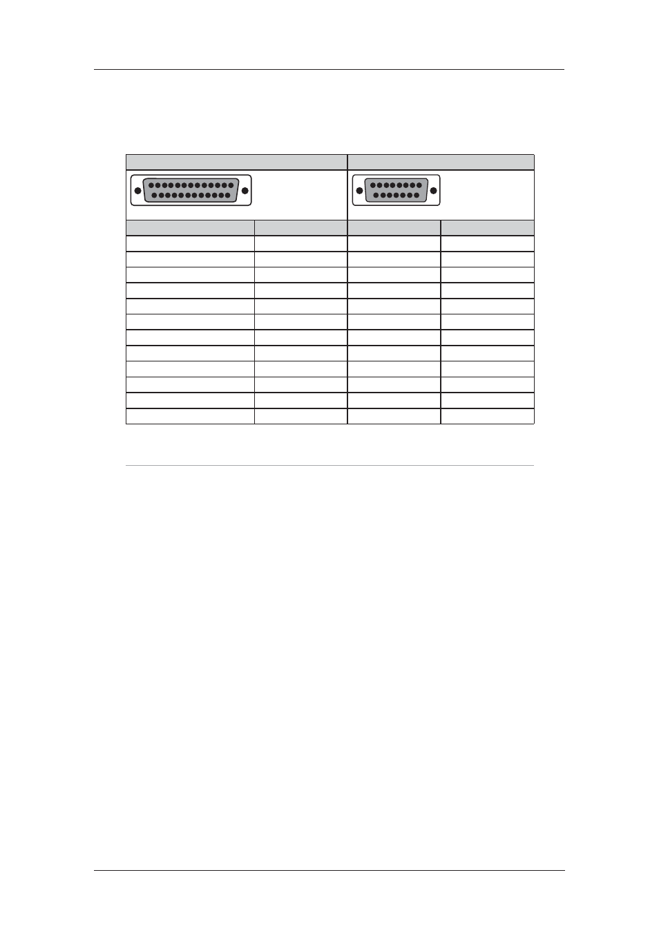
X.21 25-Pin to 15-Pin Crossover Cable – External Clock
21.1.5
This is normally the cable to use to connect the Westermo to an X.21 leased line. Use this cable
when the Westermo is the clock sink or configured as “external clock”.
25-way D - Westermo Side
15-way D
13
25
14
1
1
9
15
8
Signal
Pin # (DCE)
Pin # (DTE)
Signal
Frame Ground (Case)
Shield
Shield
Frame Ground (Case)
TxDA
2
4
RxDA
RxDA
3
2
TxDA
CTLA
4
5
INDA
INDA
5
3
CTLA
GND
7
8
GND
CLKB
11
13
CLKB
INDB
13
10
CTLB
TxDB
14
11
RxDB
RxDB
16
9
TxDB
CTLB
19
12
INDB
CLKA
24
6
CLKA
N.B. Frame Ground is optional.
Note:
When operating an X.21 (RS-422) link Synchronously it is necessary to fit termination resistors
to each signal pair at the receiving end. The Westermo already has in-built terminating resistors,
but terminating resistors will need to be fitted between the TxDA & TxDB pins, CLKA & CLKB
pins and CTLA & CTLB pins at the DTE.