1 1 milling cy cles – HEIDENHAIN CNC Pilot 4290 User Manual
Page 165
HEIDENHAIN CNC PILOT 4290
153
4.1
1 Milling Cy
cles
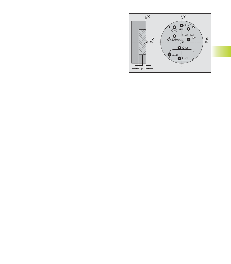
Parameters
Q:
Cycle type (= milling location)
■
Q=0: Milling center on the contour (without milling cutter
radius compensation)
■
Q=1—closed contour: inside milling
■
Q=1—with open contour: left in machining direction;
intersecting areas which are programmed in directly
successive contour elements are not machined.
■
Q=2—with closed contour: outside milling
■
Q=2—with open contour: right in machining direction;
Intersecting areas which are programmed in directly
successive contour elements are not machined.
■
Q=3 (only with open contours): The tool cuts from the left or
right of the contour depending on the “cutting direction H“
and the direction of tool rotation (see following table).
■
Q=4—with closed contour: inside milling
■
Q=4—with open contour: left in machining direction;;
Intersecting areas which are programmed in directly
successive contour elements are machined
■
Q=5—with closed contours: outside milling
■
Q=5—with open contours: right in machining direction;
Intersecting areas which are programmed in directly
successive contour elements are machined.
NS:
Block number—beginning of contour section
■
Figures: Block number of the figure.
■
“Free contour“: First contour element (not starting point).
NE:
Block number—end of contour section
■
Figures, closed contours: No input
■
Open contour: Last contour element
■
Contour consists of one element: Input unnecessary
H:
Cutting direction—default: 0
■
H=0: Up-cut milling
■
H=1: Climb milling
I:
(Maximum) infeed—default: Milling in one infeed
F:
Infeed rate (depth infeed)—default: Active feed rate
E:
Reduced feed rate for circular elements—default: Current
feed rate
R:
Radius of approaching/departing arc—default: 0
■
R=0: Contour element is approached directly; feed to
starting point above the milling plane—then vertical plunge.
■
R>0: Tool moves on an approaching/departing arc that
connects tangentially to the contour element.
■
R<0 for inside corners: Tool moves on an approaching/
departing arc that connects tangentially to the contour
element.
■
R<0 for outside corners: Contour element is approached/
departed on a tangentially linear path
P:
Milling depth
■
Milling, finishing—default: Milling depth from the contour
description
■
Deburring: Plunging depth of the tool.
K:
Retraction plane—default: return to starting
position
■
Front or rear face: Retraction position in Z
direction
■
Lateral surface: Retraction position in X
direction (diameter)
B:
Chamfer width for deburring the upper edges
(sign has no effect).
J:
Preparation diameter (tool diameter from
machining):
■
Required for deburring of open contours.
■
Not required, if diameter of deburring tool =
diameter of milling tool.
D, V: Beginning, end of element number for figures
(only if partial figures are machined).
Element numbers for figures:
Direction of contour definition for figures:
Counterclockwise.
■
Rectangles, polygons and linear slots: The
“angle of orientation” (angle with respect to the
longitudinal axis, or to one side of a polygon)
points to the first contour element.
■
Circular slot: The larger arc is the first contour
element.
■
Full circle: The upper semicircle is the first
contour element.