2 spi slave interface, 1 interface, 2 configuration – BECKHOFF EtherCAT IP Core for Xilinx FPGAs v3.00k User Manual
Page 110: Spi slave interface, Interface, Configuration, Table 47: spi signals, Figure 44: spi master and slave interconnection
PDI Description
III-98
Slave Controller
– IP Core for Xilinx FPGAs
10.2 SPI Slave Interface
10.2.1 Interface
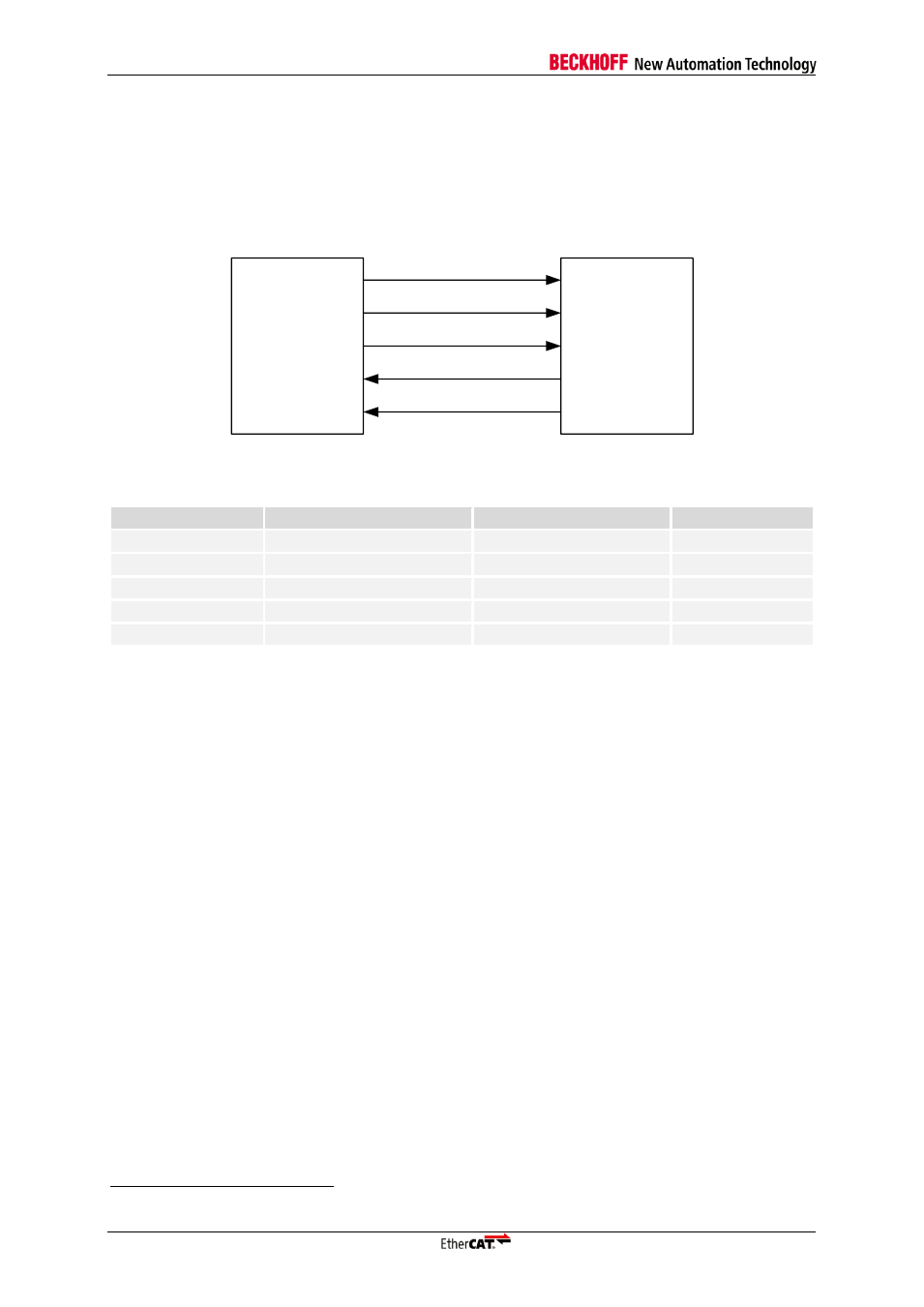
An EtherCAT device with PDI type 0x05 is an SPI slave. The SPI has 5 signals: SPI_CLK, SPI_DI
(MOSI), SPI_DO (MISO), SPI_SEL and SPI_IRQ
6
:
SPI master
(µController)
SPI_SEL
SPI_CLK
SPI_DI
SPI_DO
SPI_IRQ
SPI slave
(EtherCAT
device)
Figure 44: SPI master and slave interconnection
Table 47: SPI signals
Signal
Direction
Description
Signal polarity
SPI_SEL
IN
(master → slave)
SPI chip select
Typical: act. low
SPI_CLK
IN
(master → slave)
SPI clock
SPI_DI
IN
(master → slave)
SPI data MOSI
act. high
SPI_DO
OUT
(slave → master)
SPI data MISO
act. high
SPI_IRQ
OUT
(slave → master)
SPI interrupt
Typical: act. low
10.2.2 Configuration
The SPI slave interface is selected with PDI type 0x05 in the PDI control register 0x0140. It supports
different timing modes and configurable signal polarity for SPI_SEL and SPI_IRQ. The SPI
configuration is located in register 0x0150.
6
The prefix `PDI_` is added to the SPI signals if the EtherCAT IP Core is used.