1 mii interface signals, Mii interface signals, Table 38: mii interface signals – BECKHOFF EtherCAT IP Core for Xilinx FPGAs v3.00k User Manual
Page 93: Figure 29: mii interface signals
Ethernet Interface
Slave Controller
– IP Core for Xilinx FPGAs
III-81
9.2.1
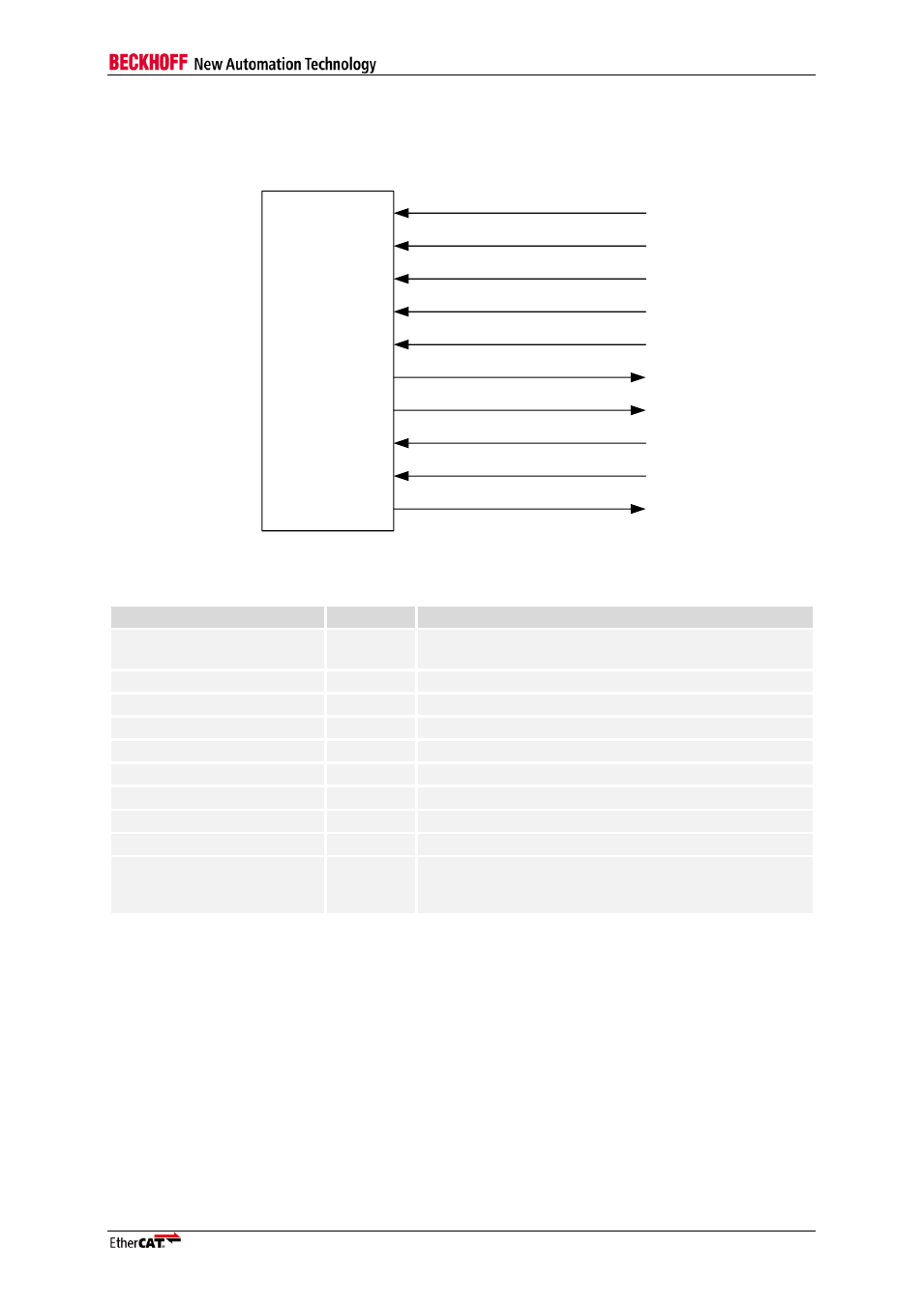
MII Interface Signals
The MII interface of the IP Core has the following signals:
EtherCAT
device
MII_RX_CLK
nMII_LINK
MII_RX_DV
MII_RX_ERR
MII_RX_DATA[3:0]
MII_TX_ENA
MII_TX_DATA[3:0]
MII_TX_CLK
MII_TX_SHIFT[1:0]
NPHY_RESET_OUT
Figure 29: MII Interface signals
Table 38: MII Interface signals
Signal
Direction
Description
nMII_LINK
IN
Input signal provided by the PHY if a 100 Mbit/s (Full
Duplex) link is established (alias LINK_MII)
MII_RX_CLK
IN
Receive Clock
MII_RX_DV
IN
Receive data valid
MII_RX_DATA[3:0]
IN
Receive data (alias RXD)
MII_RX_ERR
IN
Receive error (alias RX_ER)
MII_TX_ENA
OUT
Transmit enable (alias TX_EN)
MII_TX_DATA[3:0]
OUT
Transmit data (alias TXD)
MII_TX_CLK
IN
Transmit Clock for automatic TX Shift compensation
MII_TX_SHIFT[1:0]
IN
Manual TX Shift compensation with additional registers
NPHY_RESET_OUT
OUT
PHY reset (akt. low), resets PHY while ESC is in Reset
state, and, for FX PHYs, if Enhanced Link Detection
detects a lost link
NOTE: A pull-down resistor is typically required for NPHY_RESET_OUT to hold the PHY in reset state while the
FPGA is configured, since this pin is floating or even pulled up during that time.