9 ethernet interface, 1 phy management interface, 1 phy management interface signals – BECKHOFF EtherCAT IP Core for Xilinx FPGAs v3.00k User Manual
Page 90: 2 phy address configuration, Ethernet interface, Phy management interface, Phy management interface signals, Phy address configuration, Table 36: phy management interface signals, Figure 27: phy management interface signals
Ethernet Interface
III-78
Slave Controller
– IP Core for Xilinx FPGAs
9
Ethernet Interface
The IP Core is connected with Ethernet PHYs using MII, RMII, or RGMII interfaces. MII is
recommended since the PHY delay (and delay jitter) is smaller in comparison to RMII and RGMII.
9.1
PHY Management interface
9.1.1
PHY Management Interface Signals
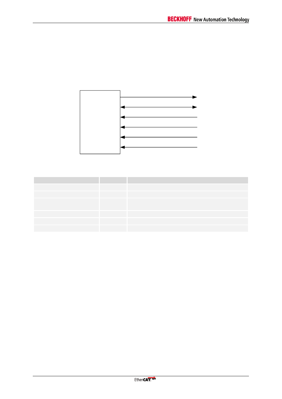
The PHY management interface of the IP Core has the following signals:
EtherCAT
device
MCLK
MDIO
PHY_OFFSET_VEC[4:0]
PHY_ADR_PORT0[4:0]
PHY_ADR_PORT1[4:0]
PHY_ADR_PORT2[4:0]
Figure 27: PHY management Interface signals
Table 36: PHY management Interface signals
Signal
Direction
Description
MCLK
OUT
Management Interface clock (alias MCLK)
MDIO
BIDIR
Management Interface data (alias MDIO)
PHY_OFFSET_VEC[4:0]
INPUT
PHY address offset (consecutive PHY addresses,
address of port 0)
PHY_ADR_PORT0[4:0]
INPUT
PHY address port 0 (individual PHY addresses)
PHY_ADR_PORT1[4:0]
INPUT
PHY address port 1 (individual PHY addresses)
PHY_ADR_PORT2[4:0]
INPUT
PHY address port 2 (individual PHY addresses)
MDIO must have a pull-up resistor (4.7 k
Ω recommended for ESCs), either integrated into the ESC or
externally. MCLK is driven rail-to-rail, idle value is High.
9.1.2
PHY Address Configuration
The EtherCAT IP Core addresses Ethernet PHYs typically using logical port number plus PHY
address offset. Ideally, the Ethernet PHY addresses should correspond with the logical port number,
so PHY addresses 0-2 are used.
A PHY address offset of 0-31 can be applied which moves the PHY addresses to any consecutive
address range. The IP Core expects logical port 0 to have PHY address 0 plus PHY address offset
(and so on).
Alternatively, the PHY addresses can be configured individually for each port.
Since the PHY addresses are static in most cases, they are set in the MegaWizard Plugin. If the PHY
addresses are changing dynamically, their configuration can be done by signals (Export PHY address
signals feature enabled).