1 configuration and resource consumption, 2 functionality, 3 implementation – BECKHOFF EtherCAT IP Core for Xilinx FPGAs v3.00k User Manual
Page 62: Configuration and resource consumption, Functionality, Implementation
Example Designs
III-50
Slave Controller
– IP Core for Xilinx FPGAs
6.1
Avnet Xilinx Spartan-6 LX150T Development Kit with Digital I/O
6.1.1
Configuration and resource consumption
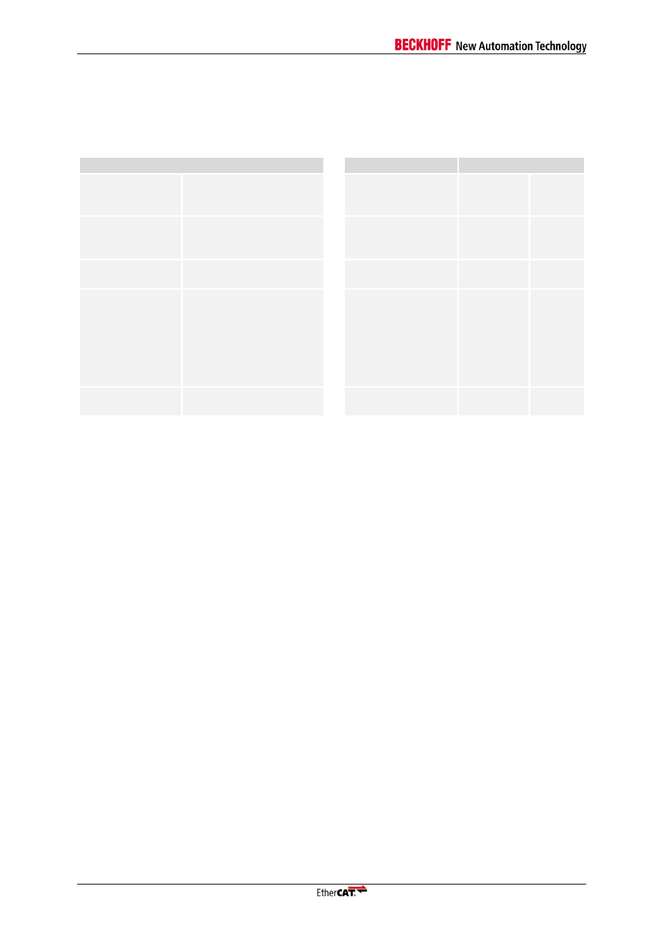
Table 13: Resource consumption Avnet LX150T example design
Configuration
Resources
XC6SLX150T
Physical layer
2x MII,
TX Shift, MIIM, Enhanced
Link Detection
Slice Registers
7,552
4 %
Internal Function
3x FMMU
4x SyncManager
1 KB RAM
Slice LUTs
8,969
9 %
Distributed clocks
32 bit,
2x Sync, 2x Latch
Occupied Slices
3,408
14 %
Feature details
Extended Watchdog,
Watchdog counter,
EPU and PDI Error
Counter,
Lost link counter,
RUN_LED,
Extended RUN/ERR LED
Block RAM
RAMB8BWER
RAMB16BWER
2
0
1 %
0 %
PDI
Digital I/O: 3 Byte IN, 1
Byte OUT
DCM
1
8 %
6.1.2
Functionality
Attach the FMC ISMNET module to FMC1 connector of LX150T base board. Populate jumper JP6
pins 1-2 (CARRIER_25MHz to CARRIER_25MHZ_S) on ISMNET, because the 25 MHz clock source
for the Ethernet PHYs is also used as the clock source for the whole system including EtherCAT IP
core in the Spartan-6 LX150T FPGA. Configure FMC IO voltage to 2.5V. You can optionally connect
the UART or the LX150T (JR1) to your PC (9600 baud, 8 bit data, 1 stop bit, no parity, no hardware
handshake). The LEDs D3 and D4 on the FMC ISMNET module are used as Link/Activity LEDs for the
two Ethernet ports.
Functionality of the Digital I/O example design:
Digital input data from push buttons SW3-SW5 on the LX150T are available in the Process Data
RAM 0x1000[2:0]
Digital input data from DIP switches SW6 on the LX150T are available in the Process Data RAM
0x1001
Digital input data from push buttons SW1-SW2 on the ISMNET module are available in the
Process Data RAM 0x1002[1:0]
Digital input data from DIP switches SW3 on the ISMNET module are available in the Process
Data RAM 0x1002[7:4]
Digital output data from Digital Output register (0x0F03) is visualized with LEDs D7-D14 on the
LX150T
DC LatchSignals are connected to push buttons SW1-SW2 on the ISMNET module
6.1.3
Implementation
1. Open Xilinx ISE
2. Open example design
<IPInst_dir>\example_designs\LX150T_DIGI.xise
3. Generate Programming File
4. Download bitstream to FPGA