Physical layer signals, Physical layer signals –2 – Altera RapidIO II MegaCore Function User Manual
Page 126
5–2
Chapter 5: Signals
Physical Layer Signals
RapidIO II MegaCore Function
August 2014
Altera Corporation
User Guide
Physical Layer Signals
Table 5–3
through
Table 5–9
list the signals to and from the Physical layer of the
RapidIO II IP core. Refer to
.
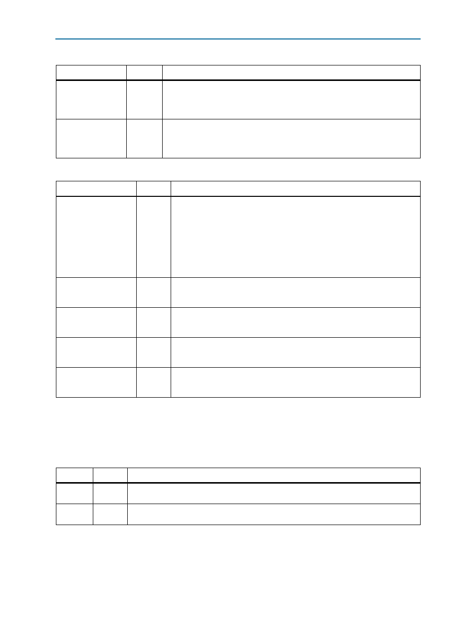
reconfig_clk_ch2
Input
Clocks the Arria 10 dynamic reconfiguration interface for RapidIO lane 2. This interface
is available in Arria 10 4x variations for which you turn on
Enable transceiver
dynamic reconfiguration
. The allowed frequency range for this clock is defined in
the
.
reconfig_clk_ch3
Input
Clocks the Arria 10 dynamic reconfiguration interface for RapidIO lane 3. This interface
is available in Arria 10 4x variations for which you turn on
Enable transceiver
dynamic reconfiguration
. The allowed frequency range for this clock is defined in
the
.
Table 5–1. Clock Signals (Part 2 of 2)
Signal
Direction
Description
Table 5–2. Global Reset Signal
Signal
Direction
Description
rst_n
Input
Active-low system reset. This reset is associated with the Avalon system clock.
rst_n
can be asserted asynchronously, but must stay asserted at least one clock
cycle and must be de-asserted synchronously with sys_clk. To reset the IP core
correctly you must also assert this signal together with the reset input signal to the
Altera Transceiver PHY Reset Controller IP core to which you must connect the
RapidIO II IP core. Refer to
“Reset for RapidIO II IP Cores” on page 4–4
.
Altera recommends that you apply an explicit 1 to 0 transition on the rst_n input
port in simulation, to ensure that the simulation model is properly reset.
reconfig_reset_ch0
Input
Resets the Arria 10 dynamic reconfiguration interface for RapidIO lane 0. This
interface is available in Arria 10 variations for which you turn on
Enable
transceiver dynamic reconfiguration
.
reconfig_reset_ch1
Input
Resets the Arria 10 dynamic reconfiguration interface for RapidIO lane 1. This
interface is available in Arria 10 2x and 4x variations for which you turn on
Enable
transceiver dynamic reconfiguration
.
reconfig_reset_ch2
Input
Resets the Arria 10 dynamic reconfiguration interface for RapidIO lane 2. This
interface is available in Arria 10 4x variations for which you turn on
Enable
transceiver dynamic reconfiguration
.
reconfig_reset_ch3
Input
Resets the Arria 10 dynamic reconfiguration interface for RapidIO lane 3. This
interface is available in Arria 10 4x variations for which you turn on
Enable
transceiver dynamic reconfiguration
.
Table 5–3. RapidIO Interface
Signal
Direction
Description
rd[n:0]
Input
Receive data—a unidirectional data receiver. It is connected to the td bus of the transmitting
device.
td[n:0]
Output
Transmit data—a unidirectional data driver. The td bus of one device is connected to the rd bus of
the receiving device.