Compiling the full design and programming the fpga – Altera RapidIO II MegaCore Function User Manual
Page 27
Chapter 2: Getting Started
2–9
Compiling the Full Design and Programming the FPGA
August 2014
Altera Corporation
RapidIO II MegaCore Function
User Guide
When you generate a RapidIO II IP core, the Quartus II software also generates the
HDL code for an ATX PLL, in the file
<variation>/altera_xcvr_atx_pll_a10_140/synth/altera_rapidio2_pll.v. However, the
HDL code for the RapidIO II IP core does not instantiate the ATX PLL. If you choose
to use the ATX PLL provided with the RapidIO II IP core, you must instantiate and
connect the ATX PLL instance with the RapidIO II IP core in user logic.
You must connect the TX PLL IP core to the RapidIO II IP core according to the
following rules.
For an example of how to configure and connect a TX PLL IP core to the other system
components, such as the external reset controller, refer to the cleartext testbench files
and
.
f
For information about the connection requirements and options, refer to the
Compiling the Full Design and Programming the FPGA
You can use the Start Compilation command on the Processing menu in the
Quartus II software to compile your design. After successfully compiling your design,
program the targeted Altera device with the Programmer and verify the design in
hardware.
1
Before compiling your design in the Quartus II software, you must perform the
modifications described in
“Adding Transceiver Analog Settings for Arria V GZ and
Stratix V Variations” on page 2–8
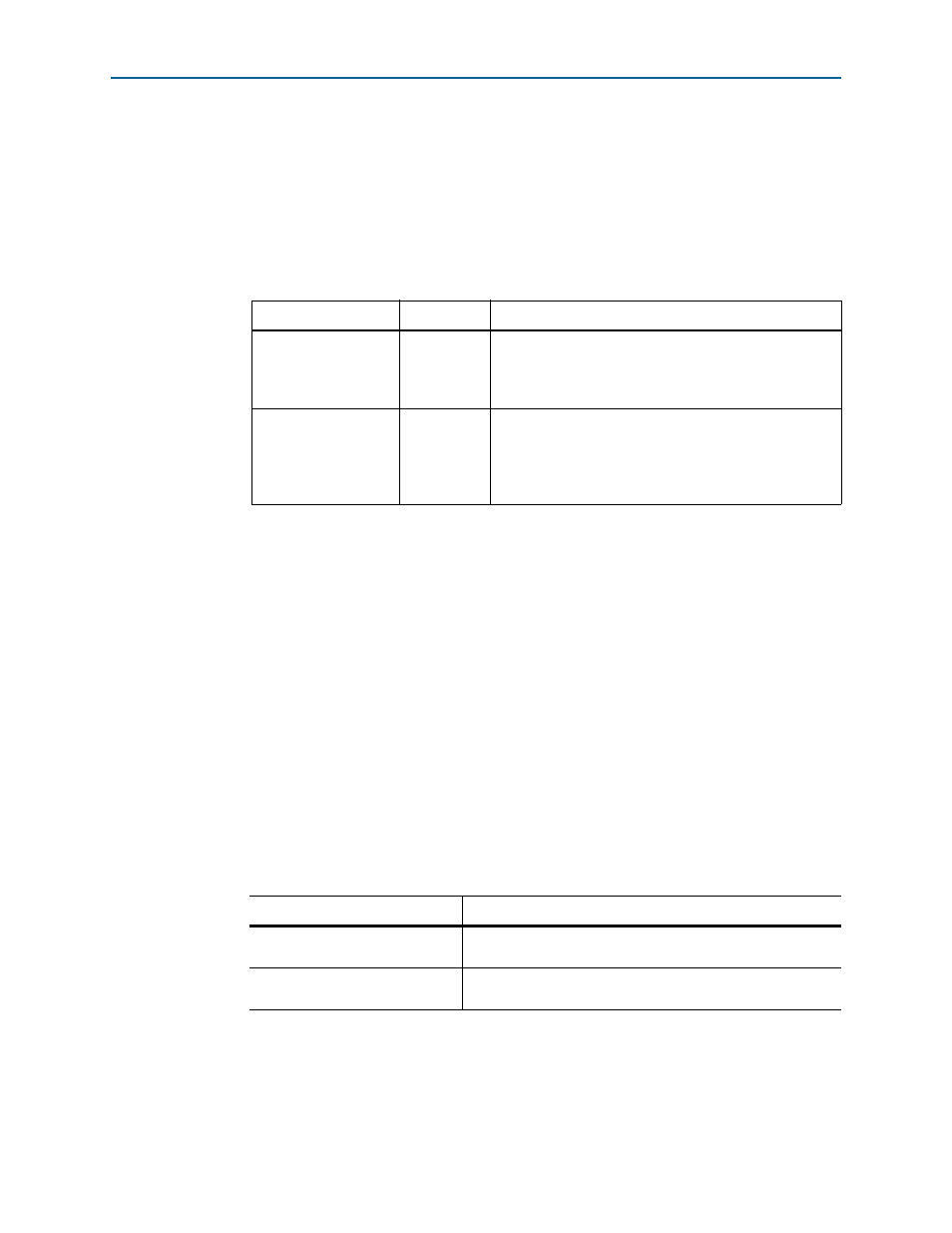
Table 2–1. External Transceiver TX PLL Connections to RapidIO II IP Core
Signal
Direction
Connection Requirements
pll_refclk0
Input
Drive the PLL pll_refclk0 input port and the RapidIO II
IP core tx_pll_refclk signal from the same clock
source. The minimum allowed frequency for the
pll_refclk0
clock in an Arria 10 ATX PLL is 100 MHz.
tx_bonding_clocks
[(6 x <number of
lanes>)–1:0]
Output
Connect tx_bonding_clocks[6n+5:6n] to the
tx_bonding_clocks_chN
input bus of transceiver
channel N, for each transceiver channel N that connects to
the RapidIO link. The transceiver channel input ports are
RapidIO II IP core input ports.
f
For Information About
Refer To
Compiling your design
r in volume 1 of the Quartus II Handbook
Programming the device
section in volume 3 of the Quartus II
Handbook