Altera RapidIO II MegaCore Function User Manual
Page 47
Chapter 4: Functional Description
4–5
Clocking and Reset Structure
August 2014
Altera Corporation
RapidIO II MegaCore Function
User Guide
■
rx_ready
, rx_analogreset, rx_digitalreset—reset the receive side of the
transceiver
■
pll_powerdown
—reset one or more Tx PLLs in the transceiver. This signal is
available in Arria V, Arria V GZ, Cyclone V, and Stratix V variations only.
In addition, if you turn on Enable transceiver dynamic reconfiguration in the
RapidIO II parameter editor, the IP core includes reconfig_reset_chN input signals.
For each N, the reconfig_reset_chN signal resets the Arria 10 Native PHY dynamic
reconfiguration interface for the transceiver channel that implements RapidIO lane N.
The reset sequence and requirements vary among device families. To implement the
reset sequence correctly for your RapidIO II IP core, you must connect the tx_ready,
tx_analogreset
, tx_digitalreset, rx_ready, rx_analogreset, rx_digitalreset, and
pll_powerdown
reset signals to an Altera Transceiver PHY Reset Controller IP core.
User logic must drive the following signals from a single reset source:
■
RapidIO II IP core rst_n (active low) input signal
■
Transceiver PHY Reset Controller IP core reset (active high) input signal
■
TX PLL pll_powerdown (active high) input signal
■
TX PLL mcgb_rst
(active high) input signal. However, Arria 10 device
requirements take precedence. Depending on the external TX PLL configuration,
your design might need to drive pll_powerdown and TX PLL mcgb_rst with
different constraints.
User logic must connect the remaining input reset signals of the RapidIO II IP core to
the corresponding output signals of the Transceiver PHY Reset Controller IP core.
f
For information about the Altera Transceiver PHY Reset Controller IP core, refer to
your target device. For details about the requirements for the
reset sequence for each device, refer to the relevant device handbook.
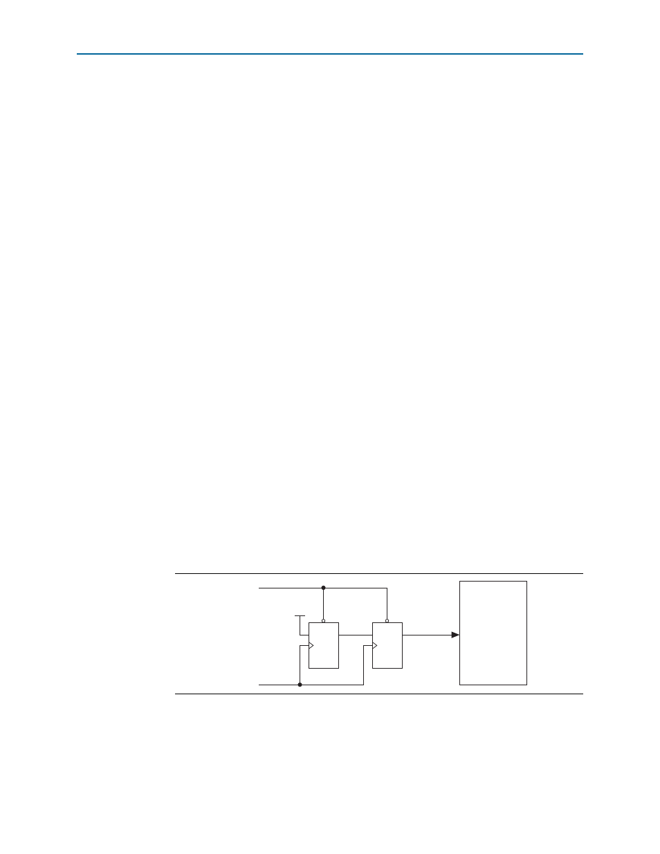
The rst_n input signal can be asserted asynchronously, but must last at least one
Avalon system clock period and be deasserted synchronously to the rising edge of the
Avalon system clock.
Figure 4–1
shows a circuit that ensures these conditions.
In systems generated by Qsys, this circuit is generated automatically. However, if
your RapidIO II IP core variation is not generated by Qsys, you must implement logic
to ensure the minimal hold time and synchronous deassertion of the rst_n input
signal to the RapidIO II IP core.
Figure 4–1. Circuit to Ensure Synchronous Deassertion of rst_n
D
D
Q
Q
rst_n
rst_n
V
CC
sys_clk
reset_n
rst_n
RapidIO II
IP Core