Input/output master interrupts, Input/output master interrupts –38, Table 6–54 – Altera RapidIO II MegaCore Function User Manual
Page 176: Table 6–51 on, Table 6–52, Table 6–53, Input/output, Table 6–51
6–38
Chapter 6: Software Interface
Transport and Logical Layer Registers
RapidIO II MegaCore Function
August 2014
Altera Corporation
User Guide
Refer to
“Defining the Input/Output Avalon-MM Master Address Mapping
for more details.
II
Input/Output Master Interrupts
describe the available Input/Output master interrupt and
corresponding interrupt enable bit. The RapidIO II IP core asserts the io_m_mnt_irq
signal if the interrupt bit is enabled.
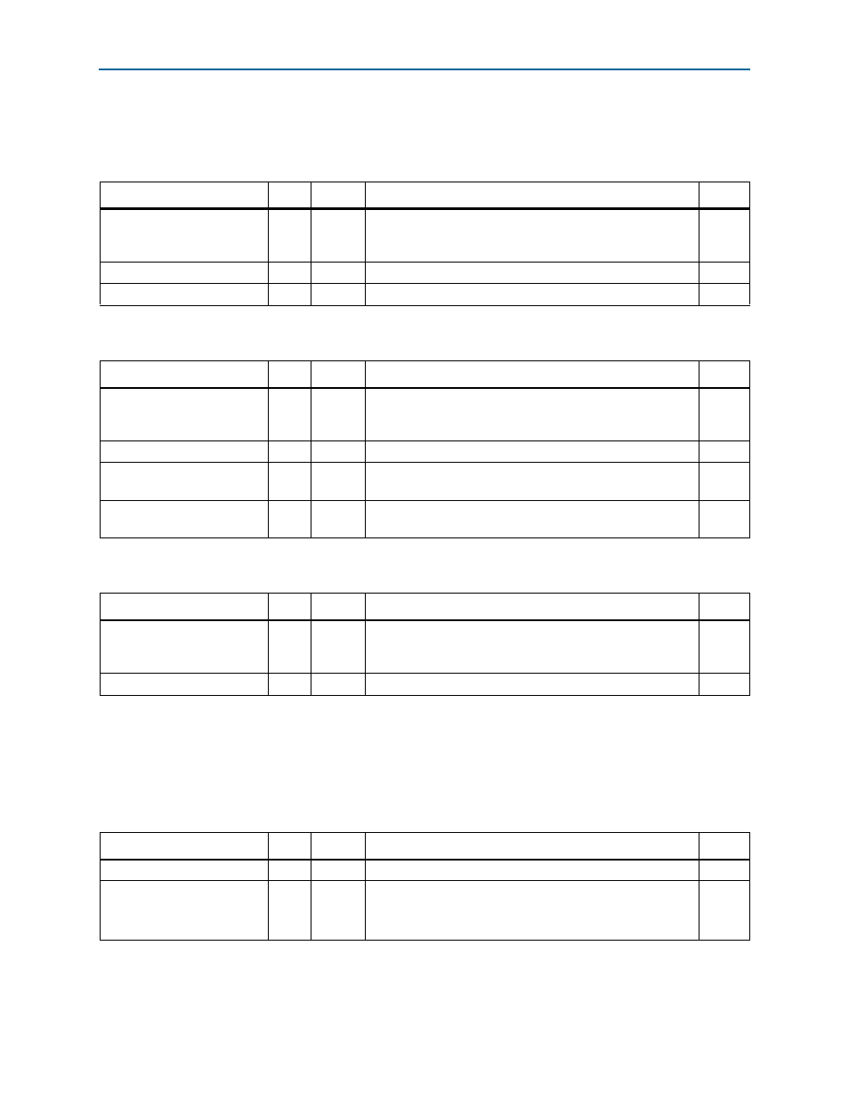
Table 6–51. Input/Output Master Mapping Window n Base—Offset: 0x10300, 0x10310, 0x10320, 0x10330, 0x10340,
0x10350, 0x10360, 0x10370, 0x10380, 0x10390, 0x103A0, 0x103B0, 0x103C0, 0x103D0, 0x103E0, 0x103F0
Field
Bits
Access
Function
Default
BASE
[31:4] RW
Start of the RapidIO address window to be mapped. The four
least significant bits of the 34-bit base are assumed to be
zeros.
28'h0
RSRV
[3:2]
RO
Reserved
2'b0
XAMB
[1:0]
RW
Extended Address: two most significant bits of the 34-bit base. 2'h0
Table 6–52. Input/Output Master Mapping Window n Mask—Offset: 0x10304, 0x10314, 0x10324, 0x10334, 0x10344,
0x10354, 0x10364, 0x10374, 0x10384, 0x10394, 0x103A4, 0x103B4, 0x103C4, 0x103D4, 0x103E4, 0x103F4
Field
Bits
Access
Function
Default
MASK
[31:4] RW
Bits 31 to 4 of the mask for the address mapping window. The
four least significant bits of the 34-bit mask are assumed to be
zeros.
28'h0
RSRV
[3]
RO
Reserved
1'b0
WEN
[2]
RW
Window enable. Set to one to enable the corresponding
window.
1'b0
XAMM
[1:0]
RW
Extended Address: two most significant bits of the 34-bit
mask.
2’b0
Table 6–53. Input/Output Master Mapping Window n Offset—Offset: 0x10308, 0x10318, 0x10328, 0x10338, 0x10348,
0x10358, 0x10368, 0x10378, 0x10388, 0x10398, 0x103A8, 0x103B8, 0x103C8, 0x103D8, 0x103E8, 0x103F8
Field
Bits
Access
Function
Default
OFFSET
[31:4] RW
Starting offset into the Avalon-MM address space. The four
least significant bits of the 32-bit offset are assumed to be
zero.
28'h0
RSRV
[3:0]
RO
Reserved
4'h0
Table 6–54. Input/Output Master Interrupt—Offset: 0x103DC
Field
Bits
Access
Function
Default
RSRV
[31:1] RO
Reserved
31'h0
ADDRESS_OUT_OF_BOUNDS
[0]
RW1C
Address out of bounds.
Asserted when the RapidIO address does not fall within any
enabled address mapping window.
1'b0