Avalon-st pass-through interface signals, Data streaming support signals – Altera RapidIO II MegaCore Function User Manual
Page 134
5–10
Chapter 5: Signals
Logical and Transport Layer Signals
RapidIO II MegaCore Function
August 2014
Altera Corporation
User Guide
Avalon-ST Pass-Through Interface Signals
This section tells you where you can find the Avalon-ST pass-through interface
signals.
lists the location of the signal lists and descriptions for the Avalon-ST
pass-through interface.
Data Streaming Support Signals
The RapidIO II IP core provides support for your custom implementation of data
streaming using the Avalon-ST pass-through interface. In addition to Error
Management Extension block signals for user-defined data streaming, the IP core
provides dedicated signals to read and write the Data Streaming Logical Layer
Control
CSR described in
Table 5–12
lists the signals provided to read and write the Data Streaming Logical
Layer Control
CSR.
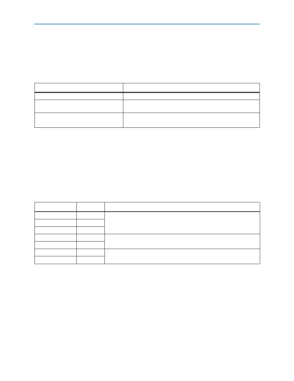
Table 5–11. Avalon-ST Pass-Through Interface Signals
Interface
Location of Signal Table
Avalon-ST sink (transmit side of the IP core)
Refer to
Avalon-ST source (receive side of the IP core):
data signals
Refer to
Avalon-ST source (receive side of the IP core):
header signals
Refer to
Table 5–12. Data Streaming Support Signals
Signal
Direction
Description
tm_types[3:0]
Output
These output signals reflect the values of the fields with the corresponding names in
the Data Streaming Logical Layer Control CSR at offset 0x48 (
).
tm_mode[3:0]
Output
mtu[7:0]
Output
tm_mode_wr
Input
Support user logic in setting the TM_MODE field in the Data Streaming Logical
Layer Control
CSR at offset 0x48,
(1)
tm_mode_in[3:0]
Input
mtu_wr
Input
Support user logic in setting the MTU field in the Data Streaming Logical Layer
Control
CSR at offset 0x48,
(1)
mtu_in[7:0]
Input
Note to
Table 5–12
:
(1) To write to the register field for any of these signal pairs, drive the value on the _in signal and then set the _wr signal to the value of 1’b1. When
the _wr signal has the value of 1’b1, on the rising edge of sys_clk, the value of the _in signal is written directly to the register field.