Altera RapidIO II MegaCore Function User Manual
Page 129
Chapter 5: Signals
5–5
Physical Layer Signals
August 2014
Altera Corporation
RapidIO II MegaCore Function
User Guide
Table 5–8
lists the Arria 10 Native PHY dynamic reconfiguration interface signals.
Each of these individual interfaces is an Avalon-MM interface you use to access the
hard PCS registers for the corresponding transceiver channel on the Arria 10 device.
These signals are available if you turn on Enable transceiver dynamic
reconfiguration
in the RapidIO II parameter editor.
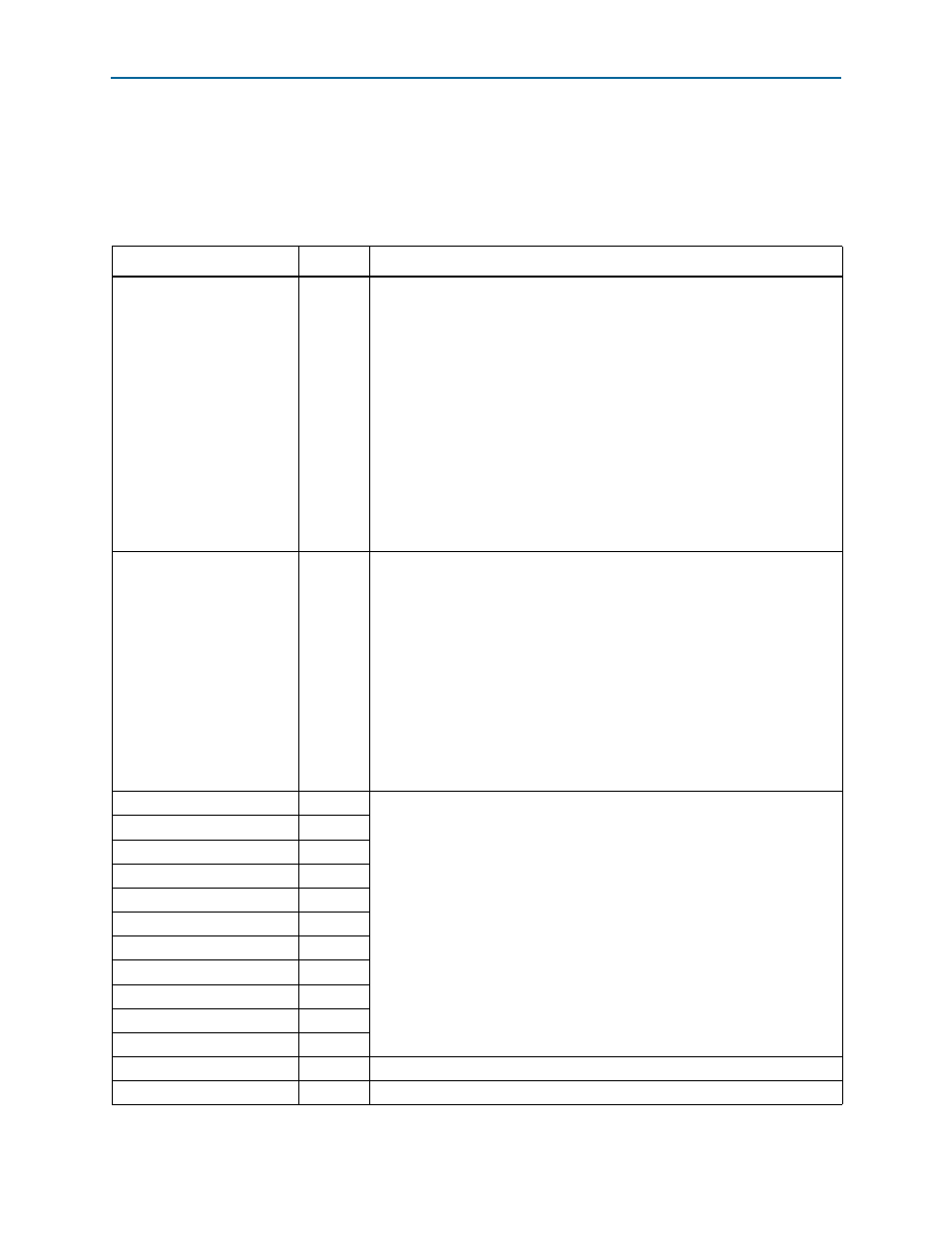
Table 5–7. Transceiver Signals (Part 1 of 2)
Signal Direction
Description
reconfig_to_xcvr
(1)
Input
Driven from an external dynamic reconfiguration block. Supports the selection
of multiple transceiver channels for dynamic reconfiguration. Note that not
using a dynamic reconfiguration block that enables offset cancellation results in
a non-functional hardware design.
The width of this bus is (C + 1) × 70, where C is the number of channels: 1, 2, or
4. This width supports communication from an Altera Reconfiguration
Controller with C + 1 reconfiguration interfaces—one dedicated to each channel
and another for the transceiver PLL—to the transceiver.
If you omit the Altera Reconfiguration Controller from your simulation model,
you must ensure all bits of this bus are tied to 0. For more information about
the Altera Reconfiguration Controller component, refer to th
This bus is available only in Arria V, Arria V GZ, Cyclone V, and Stratix V IP core
variations.
reconfig_from_xcvr
(1)
Output
Driven to an external dynamic reconfiguration block. The bus identifies the
transceiver channel whose settings are being transmitted to the dynamic
reconfiguration block. If no external dynamic reconfiguration block is used,
then this output bus can be left unconnected.
The width of this bus is (C + 1) × 46, where C is the number of channels: 1, 2, or
4. This width supports communication from the transceiver to C + 1
reconfiguration interfaces in an Altera Reconfiguration Controller, one interface
dedicated to each channel and an additional interface for the transceiver PLL.
For more information about the Altera Reconfiguration Controller component,
refer to the
This bus is available only in Arria V, Arria V GZ, Cyclone V, and Stratix V IP core
variations.
tx_cal_busy[n:0]
Output
As documented in the device-family specific Native PHY IP core chapters and
the “Transceiver PHY Reset Controller IP Core” chapter of
.
You must connect these signals to an Altera Transceiver PHY Reset Controller
IP core, which implements the appropriate reset sequence for the device.
Connect each signal to the corresponding signal in the Transceiver PHY Reset
Controller IP core.
The pll_locked and pll_powerdown signals are available only in Arria V,
Arria V GZ, Cyclone V, and Stratix V IP core variations.
rx_cal_busy[n:0]
Output
pll_locked
Output
pll_powerdown
Input
rx_digitalreset[n:0]
Input
rx_analogreset[n:0]
Input
rx_ready[n:0]
Input
tx_digitalreset[n:0]
Input
tx_analogreset[n:0]
Input
tx_ready[n:0]
Input
rx_is_lockedtodata[n:0]
Output
rx_is_lockedtoref[n:0]
Output
Indicates that the CDR is locked to tx_pll_refclk,
rx_syncstatus[n:0]
Output
Indicates that the word aligner is synchronized to incoming data.