Altera RapidIO II MegaCore Function User Manual
Page 48
4–6
Chapter 4: Functional Description
Clocking and Reset Structure
RapidIO II MegaCore Function
August 2014
Altera Corporation
User Guide
The assertion of rst_n causes the whole RapidIO II IP core to reset. The requirement
that the reset controller reset input signal and the TX PLL pll_powerdown and
mcgb_rst
input signals be asserted with rst_n ensures that the PHY IP core resets
with the RapidIO II IP core.
User logic must assert the Transceiver PHY Reset Controller IP core reset signal with
rst_n
. However, each signal is deasserted synchronously with its corresponding
clock.
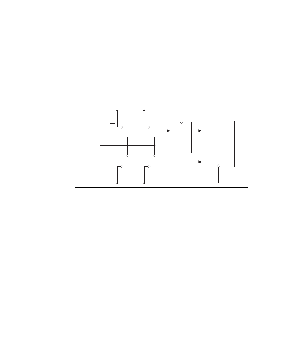
Figure 4–2
shows a circuit that ensures these conditions. In this figure, clock is
the Transceiver PHY Reset Controller IP core input clock. You can extend this logic as
appropriate to include any additional reset signals.
In systems generated by Qsys, this circuit is generated automatically. However, if
your RapidIO II IP core variation is not generated by Qsys, you must implement logic
to ensure that rst_n and reset are driven from the same source, and that each meets
the minimal hold time and synchronous deassertion requirements.
While the module is held in reset, the Avalon-MM waitrequest outputs are driven
high and all other outputs are driven low. When the module comes out of the reset
state, all buffers are empty. Refer to
for the default value
of registers after reset.
For more information about the requirements for reset signals, refer to
Consistent with normal operation, following the reset sequence, the Initialization
state machine transitions to the SILENT state. In this state, the transmitters are turned
off.
If two communicating RapidIO II IP cores are reset one after the other, one of the IP
cores may enter the Input Error Stopped state because the other IP core is in the SILENT
state while this one is already initialized. The initialized IP core enters the Input Error
Stopped state and subsequently recovers.
f
For details of the RapidIO Initialization state machine, refer to section 4.12, Port
Initialization, of Part 6: LP-Serial Physical Layer Specification of the RapidIO Interconnect
Specification, Revision 2.2, available at
.
Figure 4–2. Circuit to Also Ensure Synchronous Assertion of reset with rst_n
D
D
Q
Q
rst_n
rst_n
V
CC
sys_clk
clock
rst
rst_n
RapidIO II
IP Core
Transceiver
PHY Reset
Controller
IP Core
D
D
Q
Q
rst
rst
V
CC
reset