Transceiver level connections in the testbench, Transceiver level connections in the testbench –11, Pecially – Altera RapidIO II MegaCore Function User Manual
Page 205: Figure 7–2
Chapter 7: Testbench
7–11
Transceiver Level Connections in the Testbench
August 2014
Altera Corporation
RapidIO II MegaCore Function
User Guide
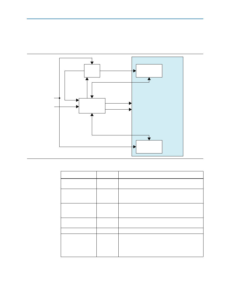
Transceiver Level Connections in the Testbench
The testbench for Arria 10 variations demonstrates one method to connect the reset
controller, the TX PLL, and the RapidIO II IP core to each other.
Figure 7–2. RapidIO II IP Core, TX PLL, and Reset Controller Connections in Arria 10 Testbench
Reset Controller
TX
PLL
Transmitter
(Native PHY)
Receiver
(Native PHY)
pll_refclk0
tx_bonding_clocks
tx_analogreset
tx_digitalreset
tx_cal_busy
rx_analogreset
rx_digitalreset
rx_is_lockedtodata
rx_cal_busy
tx_pll_refclk
reset
pll_locked
RapidIO II IP Core
tx_ready
pll_powerdown
mcg_reset
rx_ready
reference
clock
Table 7–6. External Transceiver TX PLL Connections to RapidIO II IP Core
Signal
Direction
Connection Requirements
pll_powerdown
Input
Connect pll_powerdown to the pll_powerdown[0]
output port of the reset controller.
pll_refclk0
Input
Drive the PLL pll_refclk0 input port and the RapidIO II
IP core tx_pll_refclk signal from the same clock
source.
pll_locked
Output
Connect pll_locked to the pll_locked[n] input signal
of the reset controller, for each transceiver channel n that
connects to the RapidIO link.
pll_cal_busy
Output
Drive the pll_tx_cal_busy input signal of the reset
controller.
mcgb_rst
Input
Drive mcgb_rst from the system reset signal.
tx_bonding_clocks
[6N-1:0]
where N is the number
of lanes in the IP core
variation
Ouput
Connect the TX PLL tx_bonding_clocks ouput signal bits
[6z+5:6z] to the RapidIO II IP core
tx_bonding_clocks_chz
input signal to RapidIO lane z.