Altera Video and Image Processing Suite User Manual
Page 104
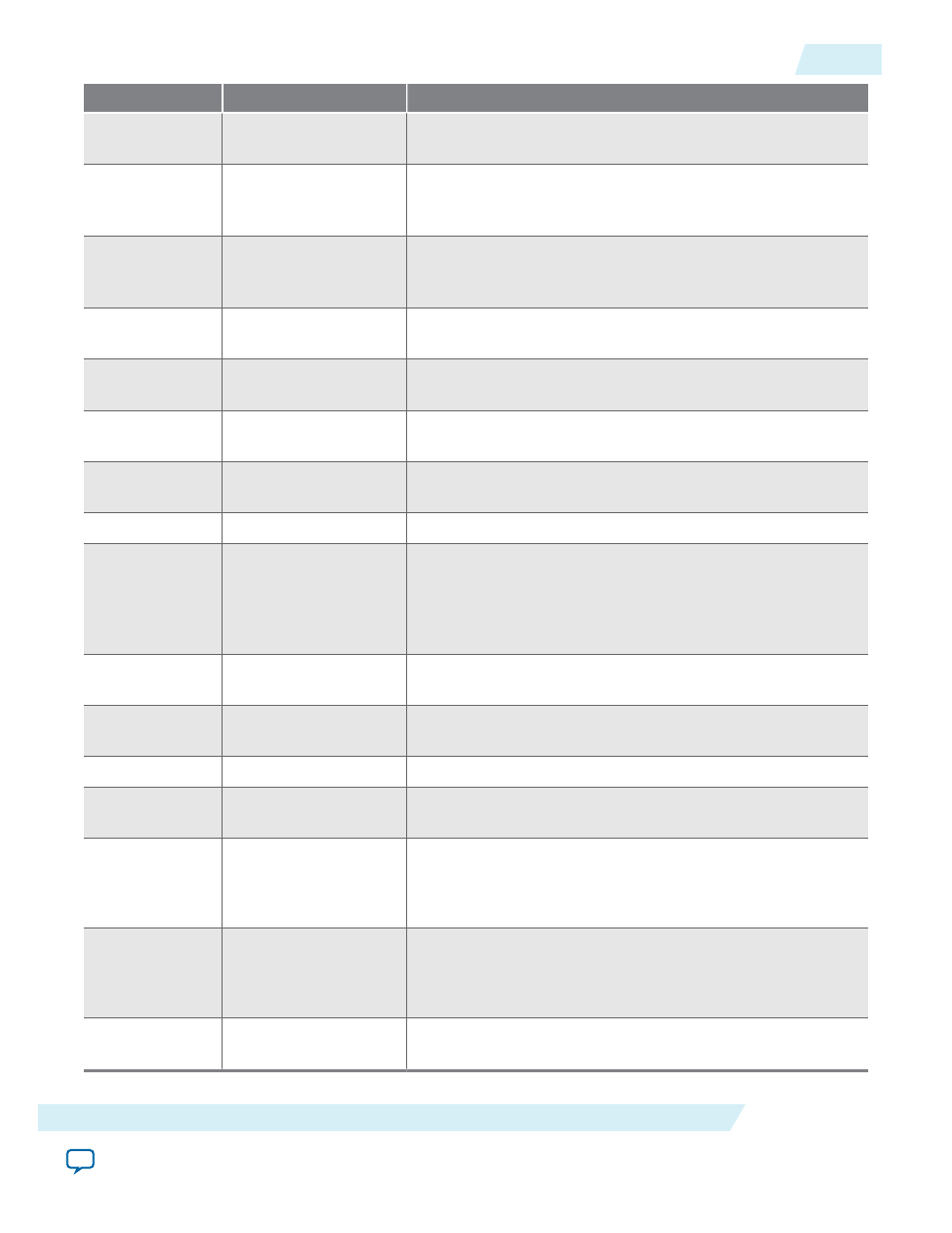
Address
Register
Description
15
Mode1 F0 Vertical
Front Porch
Video mode 1 field 0 vertical front porch (interlaced video
only). Specifies the length of the vertical front porch in lines.
16
Mode1 F0 Vertical
Sync Length
Video mode 1 field 0 vertical synchronization length
(interlaced video only). Specifies the length of the vertical
synchronization length in lines.
17
Mode1 F0 Vertical
Blanking
Video mode 1 field 0 vertical blanking period (interlaced
video only). Specifies the length of the vertical blanking period
in lines.
18
Mode1 Active Picture
Line
Video mode 1 active picture line. Specifies the line number
given to the first line of active picture.
19
Mode1 F0 Vertical
Rising
Video mode 1 field 0 vertical blanking rising edge. Specifies
the line number given to the start of field 0's vertical blanking.
20
Mode1 Field Rising
Video mode 1 field rising edge. Specifies the line number
given to the end of Field 0 and the start of Field 1.
21
Mode1 Field Falling
Video mode 1 field falling edge. Specifies the line number
given to the end of Field 0 and the start of Field 1.
22
Mode1 Standard
The value output on the
vid_std
signal.
23
Mode1 SOF Sample
Start of frame sample register. The sample and subsample
upon which the SOF occurs (and the
vid_sof
signal triggers):
• Bits 0–1 are the subsample value.
• Bits 2–15 are the sample value.
24
Mode1 SOF Line
SOF line register. The line upon which the SOF occurs
measured from the rising edge of the F0 vertical sync.
25
Mode1 Vcoclk Divider
Number of cycles of
vid_clk
(
vcoclk
) before
vcoclk_div
signal triggers.
26
Mode1 Ancillary Line
The line to start inserting ancillary data packets.
27
Mode1 F0 Ancillary
Line
The line in field F0 to start inserting ancillary data packets.
28
ModeN H-Sync
Polarity
Specify positive or negative polarity for the horizontal sync.
• Bit 0 for falling edge pulses.
• Bit 1 for rising edge hsync pulses.
29
ModeN V-Sync
Polarity
Specify positive or negative polarity for the vertical sync.
• Bit 0 for falling edge pulses.
• Bit 1 for rising edge vsync pulses.
30
ModeN Valid
Video mode valid. Set to indicate that this mode is valid and
can be used for video output.
UG-VIPSUITE
2015.05.04
Clocked Video Interface Control Registers
4-45
Clocked Video Interface IP Cores
Altera Corporation