Altera Video and Image Processing Suite User Manual
Page 97
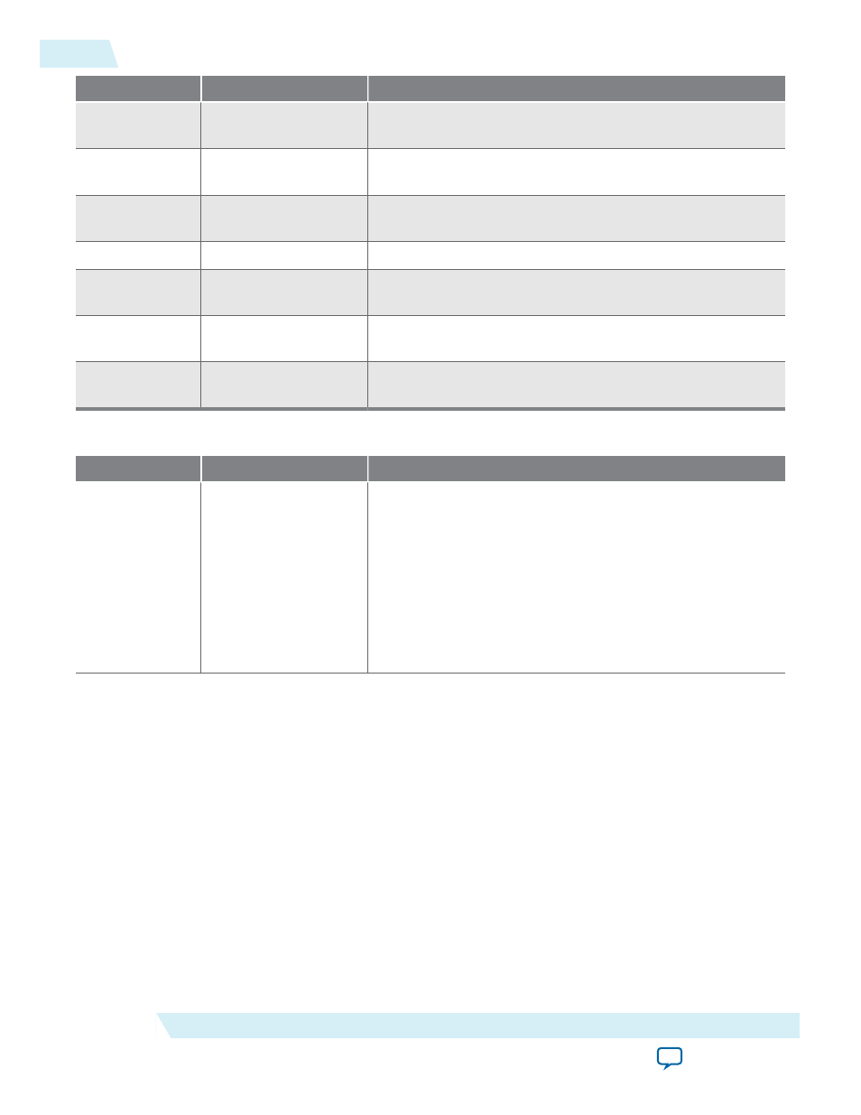
Address
Register
Description
7
Total Sample Count
The detected sample count of the video streams including
blanking.
8
F0 Total Line Count
The detected line count of the video streams F0 field including
blanking.
9
F1 Total Line Count
The detected line count of the video streams F1 field including
blanking.
10
Standard
The contents of the
vid_std
signal.
11
SOF Sample
Start of frame line register. The line upon which the SOF
occurs measured from the rising edge of the F0 vertical sync.
12
SOF Line
SOF line register. The line upon which the SOF occurs
measured from the rising edge of the F0 vertical sync.
13
Refclk Divider
Number of cycles of
vid_clk
(
refclk
) before
refclk_div
signal triggers.
Table 4-21: Clocked Video Input II Registers
Address
Register
Description
0
Control
• Bit 0 of this register is the
Go
bit:
• Setting this bit to 1 causes the CVI II IP core to start
data output on the next video frame boundary.
• Bits 3, 2, and 1 of the
Control
register are the interrupt
enables:
• Setting bit 1 to 1, enables the status update interrupt.
• Setting bit 2 to 1, enables the end of field/frame video
interrupt.
4-38
Clocked Video Interface Control Registers
UG-VIPSUITE
2015.05.04
Altera Corporation
Clocked Video Interface IP Cores