Altera Video and Image Processing Suite User Manual
Page 67
Advertising
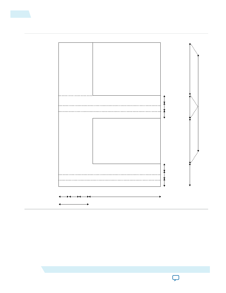
Figure 4-2: Interlaced Frame Parameters
The figure shows how the register values map to the interlaced frame format.
F0 ac
tiv
e lines
F1 ac
tiv
e lines
Ac
tiv
e lines
Active
picture line
F0 V rising
edge line
F rising
edge line
F0 active picture
F1 active picture
V front
porch
V sync
V back
porch
F0 V front
porch
F0 V sync
F0 V back
porch
V blank
ing
F0
V blank
Active samples
H back
porch
H blanking
H
sync
H front
porch
F falling
edge line
Ancillary line
F0 ancillary line
The mode registers can only be written to if a mode is marked as invalid.
4-8
Clocked Video Output Video Modes
UG-VIPSUITE
2015.05.04
Altera Corporation
Clocked Video Interface IP Cores
Advertising