Altera Video and Image Processing Suite User Manual
Page 225
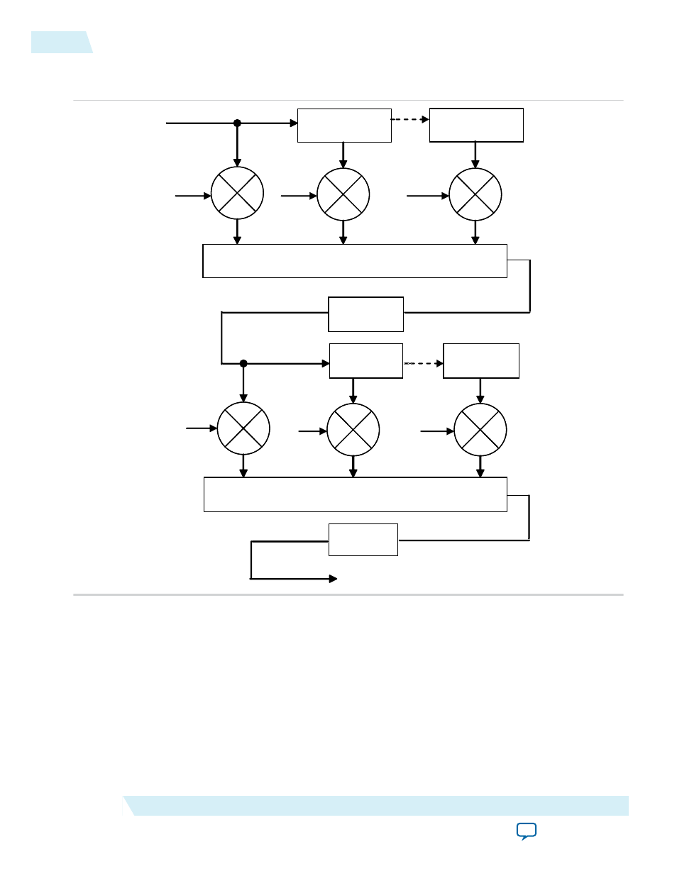
Figure 17-1: Polyphase Mode Scaler Block Diagram
The figure below shows the flow of data through an instance of the Scaler II in polyphase mode.
∑
Cv 0
Bit Narrowing
Register Delay
∑
Bit Narrowing
Line Buffer
Delay
Line Buffer
Delay
Register Delay
Ch 0
Cv 1
Cv Nv
Ch 1
Ch Nh
Data from multiple lines of the input image are assembled into line buffers–one for each vertical tap.
These data are then fed into parallel multipliers, before summation and possible loss of precision. The
results are gathered into registers–one for each horizontal tap. These are again multiplied and summed
before precision loss down to the output data bit width.
Note: The progress of data through the taps (line buffer and register delays) and the coefficient values in
the multiplication are controlled by logic that is not present in the diagram.
Consider the following for an instance of the polyphase scaler.
17-4
Polyphase and Bicubic Algorithm
UG-VIPSUITE
2015.05.04
Altera Corporation
Scaler II IP Core