Altera Video and Image Processing Suite User Manual
Page 208
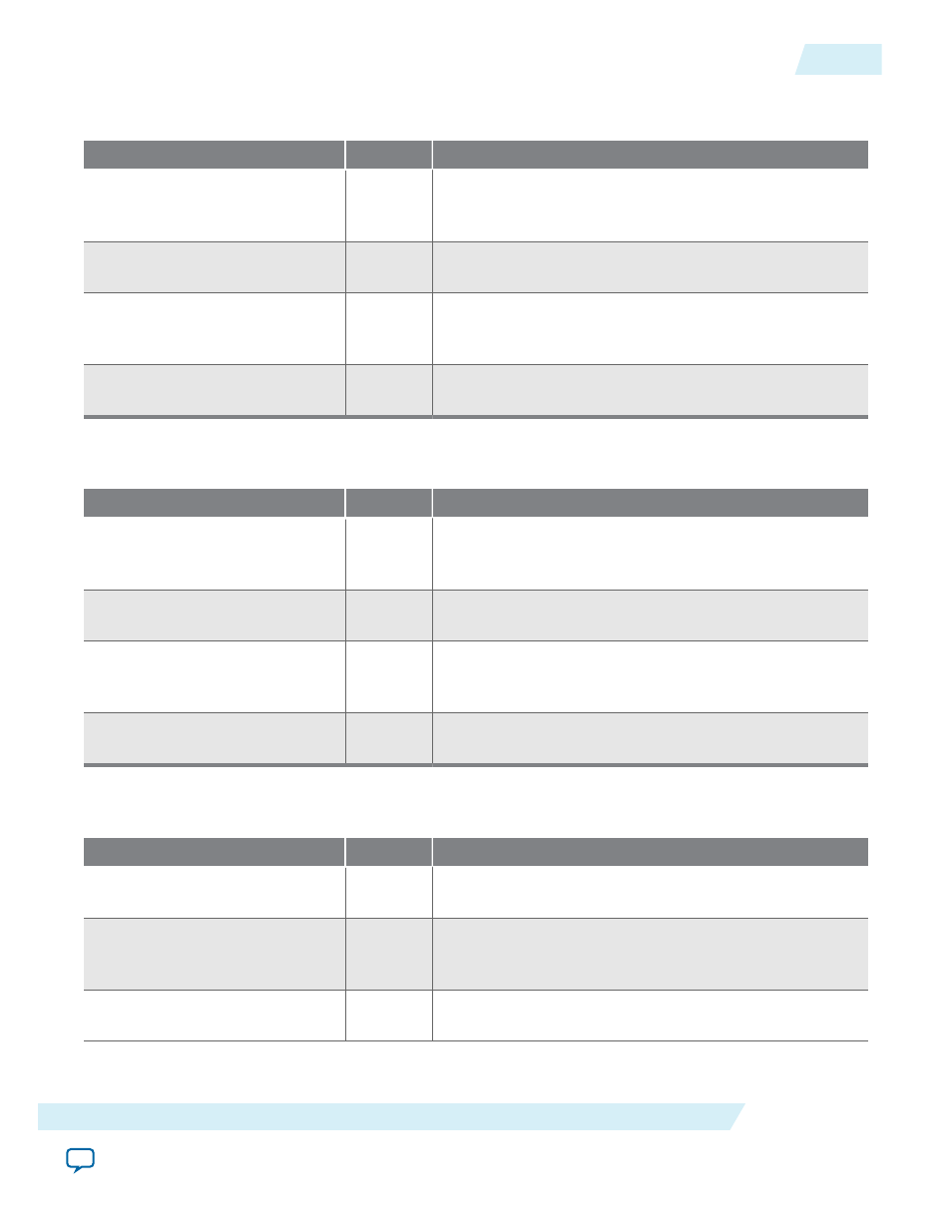
Table 14-5: Reader Control Interface Signals for Frame Buffer IP Core
These signals are present only if you turned on the control interface for the reader.
Signal
Direction
Description
reader_control_av_
chipselect
Input
reader control
slave port Avalon-MM
chipselect
signal. The
reader control
port ignores all other signals
unless you assert this signal.
reader_control_av_readdata
Output
reader control
slave port Avalon-MM
readdata
bus.
The IP core uses these output lines for read transfers.
reader_control_av_write
Input
reader control
slave port Avalon-MM
write
signal.
When you assert this signal, the
reader control
port
accepts new data from the
writedata
bus.
reader_control_av_writedata
Input
reader control
slave port Avalon-MM
writedata
bus.
The IP core uses these input lines for write transfers.
Table 14-6: Writer Control Interface Signals for Frame Buffer IP Core
These signals are present only if you enabled the control interface for the writer.
Signal
Direction
Description
writer_control_av_
chipselect
Input
writer_control
slave port Avalon-MM
chipselect
signal. The
writer_control
port ignores all other signals
unless you assert this signal.
writer_control_av_readdata
Output
writer_control
slave port Avalon-MM
readdata
bus.
The IP core uses these output lines for read transfers.
writer_control_av_write
Input
writer_control
slave port Avalon-MM
write
signal.
When you assert this signal, the
ker_writer_control
port accepts new data from the
writedata
bus.
writer_control_av_writedata
Input
writer_control
slave port Avalon-MM
writedata
bus.
The IP core uses these input lines for write transfers.
Table 14-7: Signals for Frame Buffer II IP Core
The table lists the input and output signals for the Frame Buffer IP II cores.
Signal
Direction
Description
main_clock
Input
The main system clock. The IP core operates on the rising
edge of this signal.
main_reset
Input
The IP core asynchronously resets when this signal is high.
You must deassert this signal synchronously to the rising
edge of the clock signal.
mem_clock
Input
mem_master
port
clock
signal. The interface operates on
the rising edge of the
clock
signal.
UG-VIPSUITE
2015.05.04
Frame Buffer Signals
14-11
Frame Buffer IP Cores
Altera Corporation