Altera Video and Image Processing Suite User Manual
Page 75
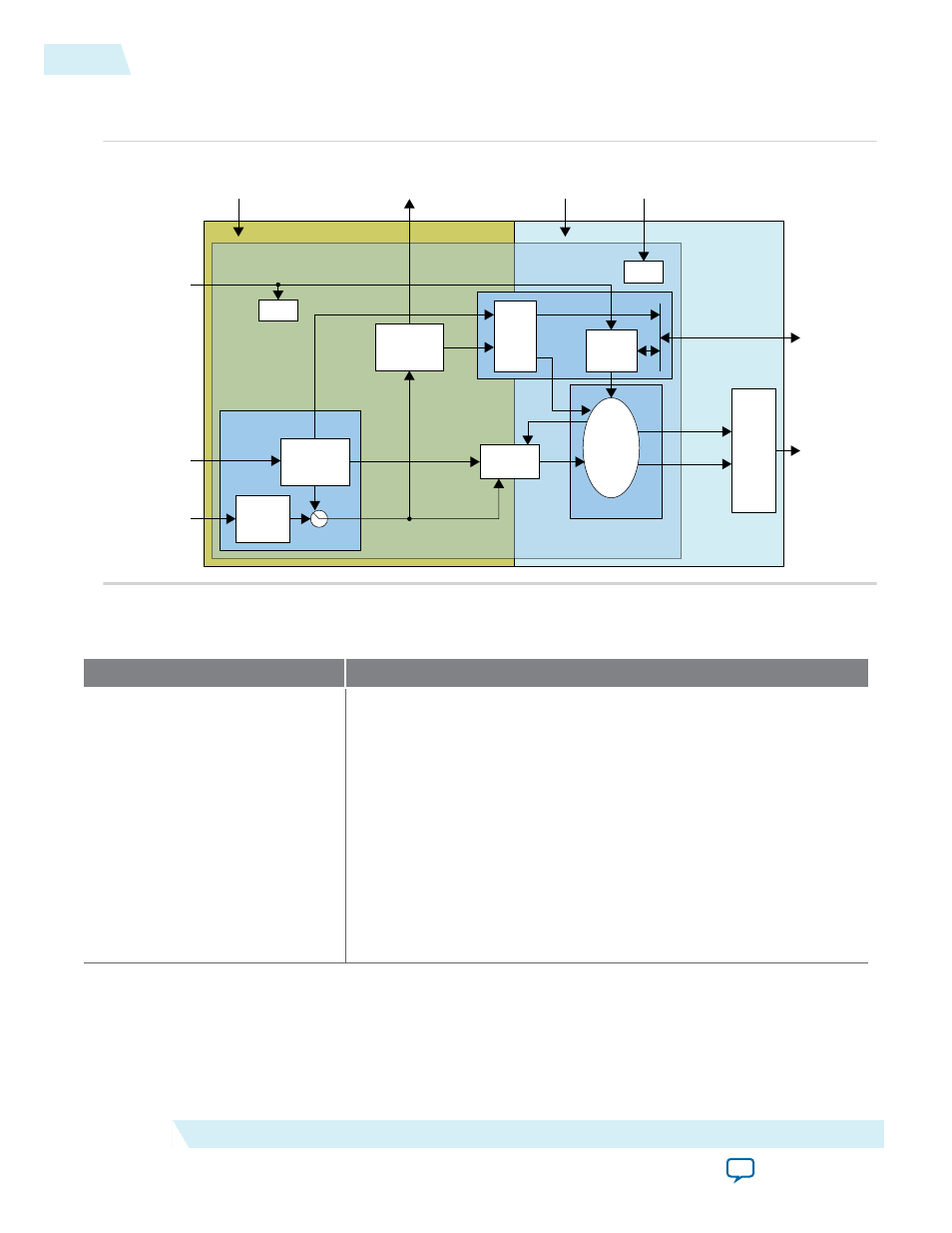
Figure 4-5: Block Diagram for Clocked Video Input II IP Core
The figure below shows a block diagram of the Clocked Video Input II IP core architecture.
Sync
Polarity
Convertor
Embedded
Sync Extractor
Sync
Signals
vid_data
vid_datavalid
vid_v_sync
vid_h_sync
vid_f
Sync Conditioner
Reset
Resolution
Detection
Write Buffer
FIFO
RAM
Registers
Reset
State
Machine
Width
Height
Video
Data
Video
Data
Avalon-ST Output
Control
rdreq
Video
Output
Bridge
Control
Packets
Video
Packets
Avalon-ST
Video
Avalon-MM
Slave
rst
ls_clk
vid_clk
sof
sof_locked
refclk_div
Auxiliary Packets
Core
h_sync
v_sync
f
de
vid_locked
Table 4-9: Modules for Clocked Video Input II IP Core
The table below describes the modules in the Clocked Video Input II IP core architecture.
Modules
Description
Sync_conditioner
• In embedded sync mode, this module extracts the embedded syncs
from the video data and produces
h_sync
,
v_sync
,
de
, and
f
signals.
• The module also extracts any ancillary packets from the video and
writes them into a RAM in the control module.
• In separate sync modes, this module converts the incoming sync
signals to active high and produces
h_sync
,
v_sync
,
de
, and
f
signals.
• If you turn on the Extract field signal parameter, the
f
signal is
generated based on the position of the V-sync. If the rising edge of
the V-sync occurs when
h_sync
is high, then the
f
signal is set to 1,
otherwise it is set to 0.
4-16
Modules for Clocked Video Input II IP Core
UG-VIPSUITE
2015.05.04
Altera Corporation
Clocked Video Interface IP Cores