Avalon-mm slave interfaces, Avalon-mm slave interfaces -25 – Altera Video and Image Processing Suite User Manual
Page 52
Example 3 (Control Data Transfer)
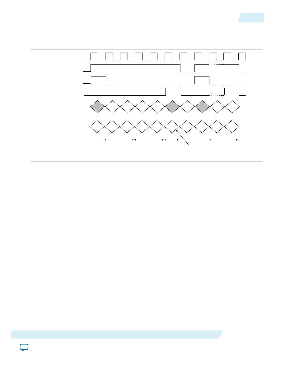
Figure 2-18: Timing Diagram Showing Control Packet Transfer
This figure shows the transfer of a control packet for a field of 720×480 video (with field height 240).
clock
din_valid
din_startofpacket
CbCr din_data(13:10)
0x2
din_endofpacket
Y din_data(3:0)
0x0
0x0
0x0
0x0
0x0
0xD
0xF
0x0
0xF
10xx
720(0x02D0)
240(0x00F0)
image data
if0
binary
f0 - 10xx
f1 - 11xx
p - 00xx
The packet is transferred over an interface configured for 10-bit data with two color planes in parallel.
Each word of the control packet is transferred in the lowest four bits of a color plane, starting with bits 3:0,
then 13:10.
Avalon-MM Slave Interfaces
The Video and Image Processing Suite IP cores that permit run-time control of some aspects of their
behavior, use a common type of Avalon-MM slave interface for this purpose.
Each slave interface provides access to a set of control registers which must be set by external hardware.
You must assume that these registers power up in an undefined state. The set of available control registers
and the width in binary bits of each register varies with each control interface.
UG-VIPSUITE
2015.05.04
Avalon-MM Slave Interfaces
2-25
Interfaces
Altera Corporation