Avalon-st video monitor signals, Avalon-st video monitor signals -4 – Altera Video and Image Processing Suite User Manual
Page 265
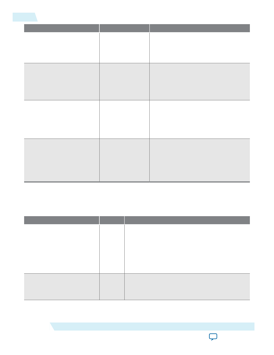
Parameter
Value
Description
Color planes transmitted in
parallel
On or Off
• Turn on to transmit all the color planes at
the same time in parallel.
• Turn off to transmit all the color planes in
series.
Pixels in parallel
1, 2, or 4
Specify the number of pixels in parallel that
the video pipeline is configured for.
Note: You must specify this parameter
value to 1 to capture video data
frames.
Bit width of capture interface(s) • 8
• 16
• 32
• 64
• 128
Select the data bus width of the Avalon-ST
interface sending the captured information.
Capture video pixel data
On or Off
Turn on to enable the inclusion of hardware
that allows the monitor to capture video data
frames.
Note: This parameter only functions if
you specify the number of pixels in
parallel to a value of 1.
Avalon-ST Video Monitor Signals
Table 21-3: Avalon-ST Video Monitor Signals
Signal
Direction
Description
clock_clk
Input
All signals on the monitor are synchronous to this clock.
Drive this signal from the clock which drives the video
components that are being monitored.
Note: Do not insert clock crossing between the
monitor and the trace system component. You
must drive the trace system’s clock from the
same source which drives this signal.
reset_reset
Input
This signal only resets the debugging parts of the monitor.
It does not affect the system being monitored. Drive this
signal directly from the
reset_reset
output of the trace
system component.
21-4
Avalon-ST Video Monitor Signals
UG-VIPSUITE
2015.05.04
Altera Corporation
Avalon-ST Video Monitor IP Core