Altera Video and Image Processing Suite User Manual
Page 49
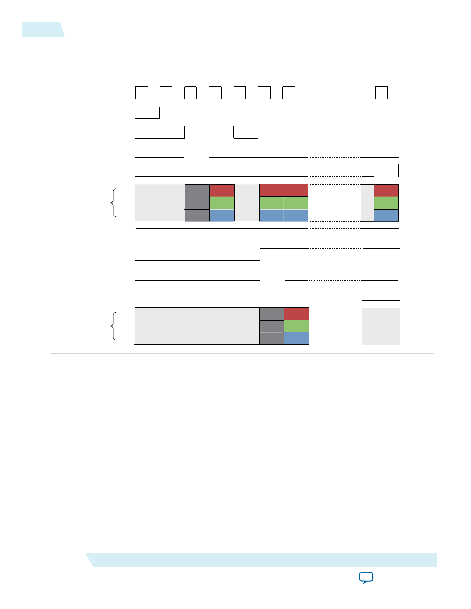
Figure 2-16: Timing Diagram Showing R’G’B’ Transferred in Parallel
The figure below shows how the first few pixels of a frame are processed.
clock
din_ready
din_startofpacket
din_valid
din_data
23:16
15:8
7:0
dout_ready
dout_valid
dout_endofpacket
dout_data
23:16
15:8
7:0
1.
2.
3.
4.
5.
6.
7.
B
0,0
G
0,0
R
0,0
B
1,0
B
2,0
G
2,0
R
1,0
B
2,0
G
1,0
B
0,0
G
0,0
R
0,0
B
x,y
G
x,y
R
x,y
n.
X
X
0
din_endofpacket
dout_startofpacket
X
X
0
This example has one Avalon-ST port named din and one Avalon-ST port named dout. Data flows into
the IP core through din, is processed and flows out of the IP core through
dout
.
There are five signals types—ready, valid, data, startofpacket, and endofpacket—associated with each port.
The
din_ready
signal is an output from the IP core and indicates when the input port is ready to receive
data. The
din_valid
and
din_data
signals are both inputs. The source connected to the input port sets
din_valid
to logic '1' when
din_data
has useful information that must be sampled. The
din_startof-
packet
signal is an input that is raised to indicate the start of a packet, with
din_endofpacket
signaling
the end of a packet. The five output port signals have equivalent but opposite semantics.
The sequence of events for this example:
1. Initially,
din_ready
is logic '0', indicating that the IP core is not ready to receive data on the next cycle.
Many of the Video and Image Processing Suite IP cores are not ready for a few clock cycles in between
rows of image data or in between video frames.
2. The IP core sets
din_ready
to logic '1', indicating that the input port is ready to receive data one clock
cycle later. The number of clock cycles of delay which must be applied to a ready signal is referred to as
2-22
Packet Transfer Examples
UG-VIPSUITE
2015.05.04
Altera Corporation
Interfaces