Subway wlan mesh deployment – H3C Technologies H3C WX3000E Series Wireless Switches User Manual
Page 323
307
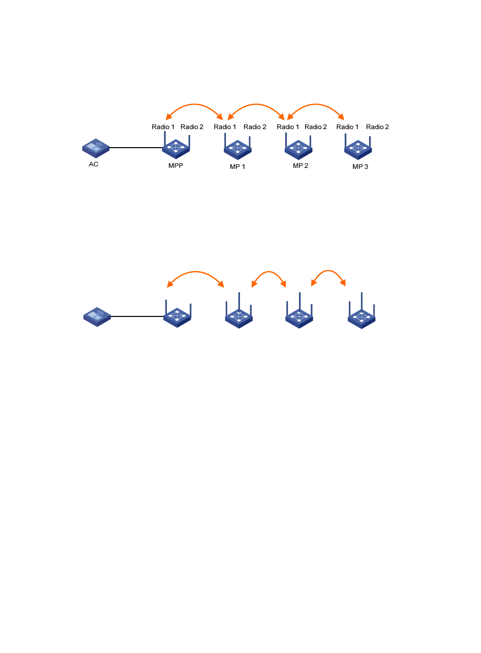
As shown in
, Radio 1 of MP 1 joins the mesh through the MPP. In this case, only Radio
1 can provide access for downstream MPs. Radio 2 cannot automatically access the mesh and
provide the mesh service.
Figure 324 Two radios on different meshes
If an MP supports three radios, you can configure Radio 1 as the uplink interface, Radio 2 as the
downlink interface, and Radio 3 as the multi-beam antenna. To utilize the dual-radio resources on
MPs, you can establish the network as shown in
. In such a network, when Radio 1 of
MP 1 accesses the mesh, Radio 2 on MP 1 also automatically joins the mesh. In this network, you
should apply the same mesh service to both Radio 1 and Radio 2. For more information, see
"
Tri-radio mesh configuration example
."
Figure 325 Two radios on the same mesh
Subway WLAN mesh deployment
A subway is an important traffic means for a modern city. In a subway system, control information must
be sent to trains to effectively manage trains and provide various services to customers.
As shown in
, a subway WLAN mesh solution has fit MPs deployed along the rail, which are
managed by the same AC. A train MP (fat AP) continuously scans new rail MPs (fit APs), and sets up
active/dormant links with the rail MPs with the best signal quality. The active mesh link is used for data
transmission, and the dormant mesh link acts as the backup link.
AC
MPP
MP 1
MP 2
Radio 1
Radio 1
Radio 1
Radio 2
Radio 2
Radio 2
MP 2
Radio 1 Radio 2
Radio 3
Radio 3
Radio 3