Hypertherm Phoenix 8.0 User Manual
Page 528
Automatic DXF Import
521
DL 225
° to 270°
D 260
° to 280°
DR 270
° to 315°
RD 315
° to 360°
Traverses are automatically determined between pierce points and do not need to be
entered on the CAD drawing.
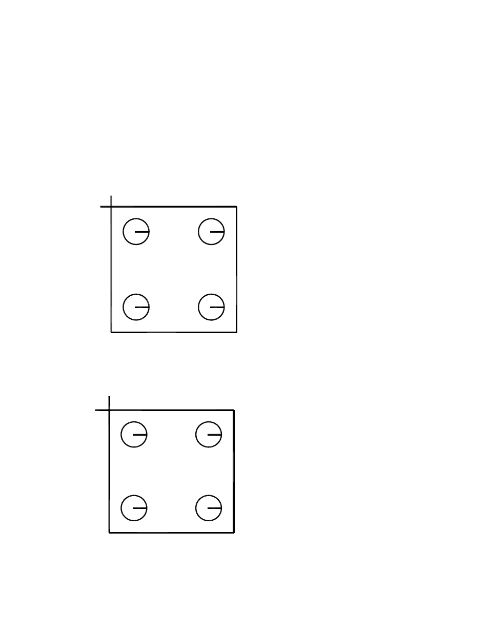
The following example is a basic bolt hole rectangle with the lead-in and lead-out for the
rectangle as part of the top and side line segments. The numbers indicate the order of the
pierces and the “+” sign indicates a counter-clockwise rotation for the circles.
+
+
+
+
1
2
3
4
5
If the lead-in and lead-out are created as additional line segments added to the top and
side line segments, additional text is required to indicate which direction the next line
segment should take as part of the part program, as shown in the following diagram:
+
+
+
+
1
2
3
4
R
5
In this example, the letter “R” has been snapped to the intersection of the four line
segments to indicate that the next line segment after lead-in (pierce 5) would be the