Basler Electric DECS-400 User Manual
Page 103
9369700990 Rev R
91
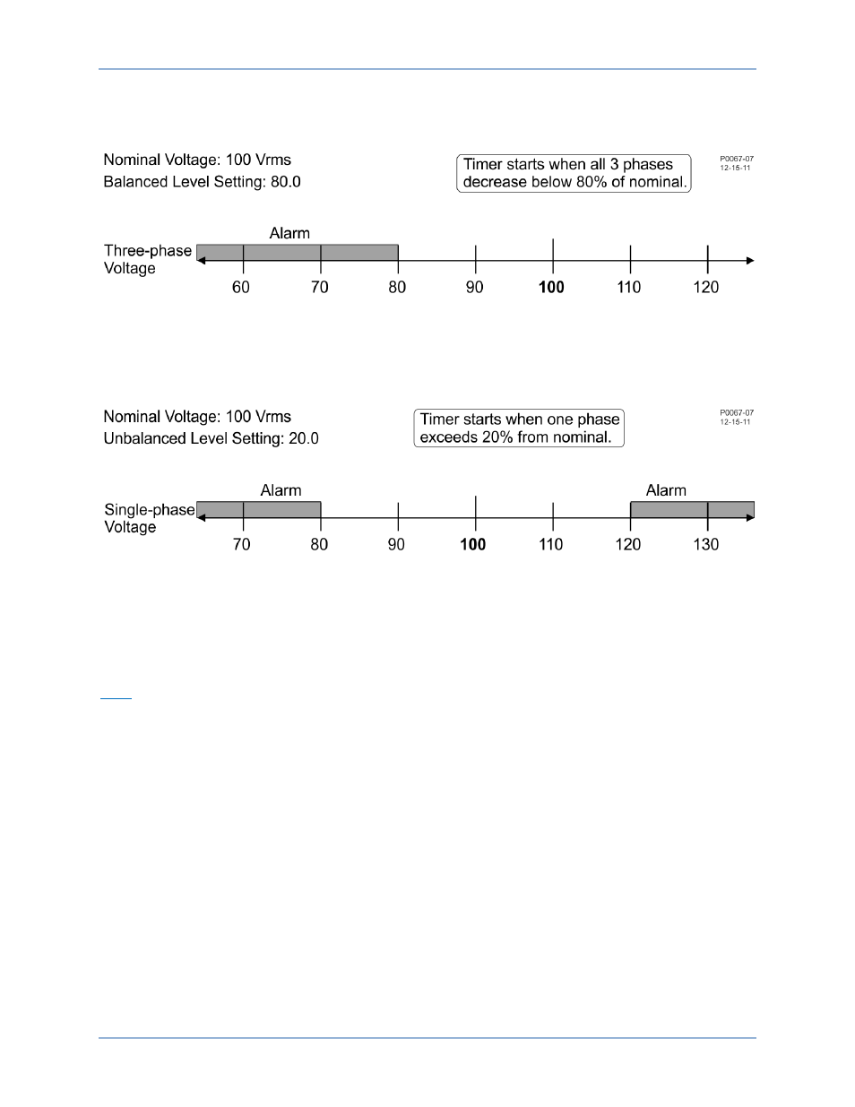
Loss of Sensing Voltage – Balanced Level. When all three phases of sensing voltage decrease below this
setting, the loss of sensing time delay begins timing out. A setting of 0 to 100 percent (of nominal) may be
entered in 0.1 percent increments. Refer to the example in Figure 57.
Figure 57. Example of Balanced Level Threshold
Loss of Sensing Voltage – Unbalanced Level. When the absolute difference between the average of all
three phases and any one of the three phases of sensing voltage exceeds this setting, the loss of sensing
voltage time delay begins timing out. A setting of 0 to 100 percent (from nominal) may be entered in 0.1
percent increments. Refer to the example in Figure 58.
Figure 58. Example of Unbalanced Level Threshold
Loss of Sensing Voltage – Delay. This setting determines the length of time between when a loss of
sensing voltage condition is detected and annunciated. A setting of 0 to 30 seconds may be entered in
0.1 second increments.
Loss of Sensing Voltage – Transfer to FCR. This setting enables and disables the transfer to FCR mode
when a loss of sensing voltage condition is detected.
EDM
EDM tab settings are shown in Figure 59 and described in the following paragraphs.
Pole Ratio. The ratio of the number of exciter field poles to the number of main field poles is entered in
this setting field. A value of 0 to 40.00 may be entered in 0.01 increments.
DECS-400
BESTCOMS™ Software