Volts per hertz limiter – Basler Electric DECS-400 User Manual
Page 60
48
9369700990 Rev R
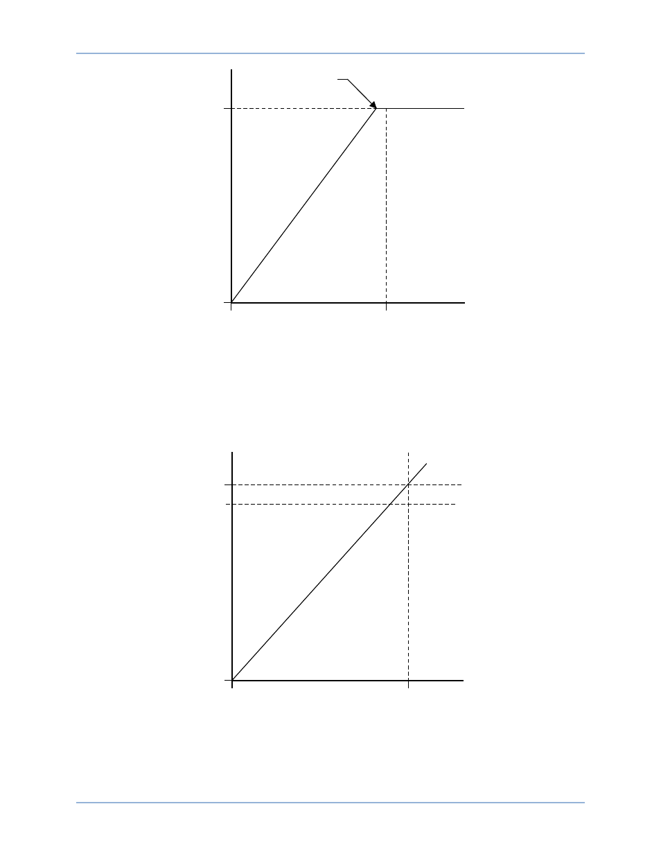
Figure 16. Typical Underfrequency Compensation Curve
Volts per Hertz Limiter
The volts per hertz limiter prevents the regulation setpoint from exceeding the volts per hertz ratio defined
by the DECS-400 underfrequency slope setting. Volts per hertz ratio limiting guards against reduced
frequency situations and changes in system voltage. A typical volts per hertz limiter curve is illustrated in
Figure 17.
Figure 17. Typical 1.1 PU Volts/Hertz Limiter Curve
Beside the underfrequency slope setting, volts per hertz limiter operation is determined by the V/Hz High
Limiter setting, the V/Hz Low Limiter setting, and the V/Hz Time Limiter setting. The V/Hz High Limiter
setting establishes the maximum threshold for the volts per hertz limiter and can be adjusted from 0 to 3
in increments of 0.01. The V/Hz Low Limiter setting establishes the minimum threshold for the volts per
Corner Frequency
G
EN
ER
AT
O
R
VO
L
T
S
GENERATOR FREQUENCY
P0004-34.vsd
12-03-01
0 %
100 %
Nominal
10 Hz
V
ol
ts
/H
er
tz
R
ati
o
G
EN
ER
AT
O
R
VO
L
T
S
GENERATOR FREQUENCY
P0004-33.vsd
12-03-01
0 %
110 %
Nominal
0 Hz
100 %
Functional Description
DECS-400