Basler Electric DECS-400 User Manual
Page 107
9369700990 Rev R
95
Washout Filter Time Constant. This setting can be used to tailor the response of the PSS rate-of-change
function to the application. A setting of 0 to 20 seconds may be entered in 0.01 second increments.
Control
The Control tab has two setting groups: Primary and Secondary. These two groups are selected with the
Primary and Secondary buttons. In the default, PSS logic schemes provided with the DECS-400, a
contact input is used to select between the primary and secondary PSS settings. (Primary/secondary
gains are automatically selected when the PSS becomes active.)
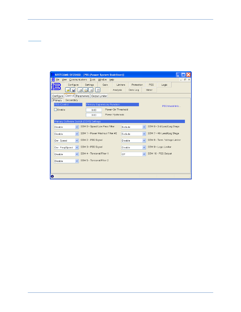
Control tab settings are shown in Figure 64 and described in the following paragraphs.
Figure 64. PSS Screen, Control Tab
PSS Control – Enable. This setting enables and disables the power system stabilization by the DECS-
400. This setting is available only when the primary settings of the Control tab are displayed.
Supervisory Function – Power-On Threshold. This setting defines the power level (watts) required to
enable power system stabilizer operation. The Power On Threshold is a per-unit setting that is based on
the Generator Rated Data settings entered on the Rated Data tab of the BESTCOMS System
Configuration screen. A setting of 0 to 1.00 may be entered in increments of 0.01.
Supervisory Function – Power Hysteresis. This setting provides a margin below the power-on threshold
setting so that transient dips in power (watts) will not disable power system stabilizer operation. The per-
unit Power Hysteresis setting is based on the Generator Rated Data settings entered on the Rated Data
tab of the BESTCOMS System Configuration screen. A setting of 0 to 1.00 may be entered in increments
of 0.01.
PSS Model Info. Clicking this link opens a window displaying the function blocks and software switches of
the DECS-400 PSS function.
Software Switch Settings – SSW 0, Speed Low Pass Filter. This setting enables and disables the power
system stabilizer speed input low-pass filter.
Software Switch Settings – SSW 1, Power Washout Filter #2. This setting enables and disables the
washout filter of the power system stabilizer power input.
Software Switch Settings – SSW 2, PSS Signal. This setting selects either derived speed or frequency as
the power system stabilizer signal.
DECS-400
BESTCOMS™ Software