N figure 69 – Basler Electric DECS-400 User Manual
Page 113
9369700990 Rev R
101
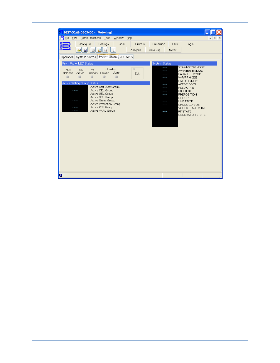
Figure 69. Metering Screen, System Status Tab
Front Panel LED Status. These indicators mirror the front panel indicator LEDs on the DECS-400 front
panel. An indicator changes from gray to red when the corresponding front panel LED lights.
Active Setting Group Status. Setting groups are listed (Figure 69) alongside text labels that change
according to the status (primary or secondary) of each setting group.
System Status. Various system operating modes (Figure 69) are listed alongside text labels that change
according to the status of each operating mode.
I/O Status
I/O Status tab indicators are shown in Figure 70 and described in the following paragraphs.
Switch Input Status. These indicators annunciate the status (open or closed) of each DECS-400 contact
input. An open switch input is indicated by a gray indicator; a closed switch input is indicated by a green
indicator.
Relay Output Status. These indicators annunciate the status of each DECS-400 contact output. A de-
energized relay is indicated by a gray indicator; an energized relay is indicated by a red indicator.
Set Programmable Labels. Clicking this button opens the Programmable I/O Labels screen which enables
user-defined labels to be assigned to the DECS-400 contact inputs and outputs. Each input/output can be
assigned a label containing a maximum of 21 alphanumeric characters.
System Status. Various system operating modes (Figure 70) are listed alongside text labels that change
according to the status of each operating mode.
DECS-400
BESTCOMS™ Software