Basler Electric DECS-400 User Manual
Page 130
118
9369700990 Rev R
FCR Tab
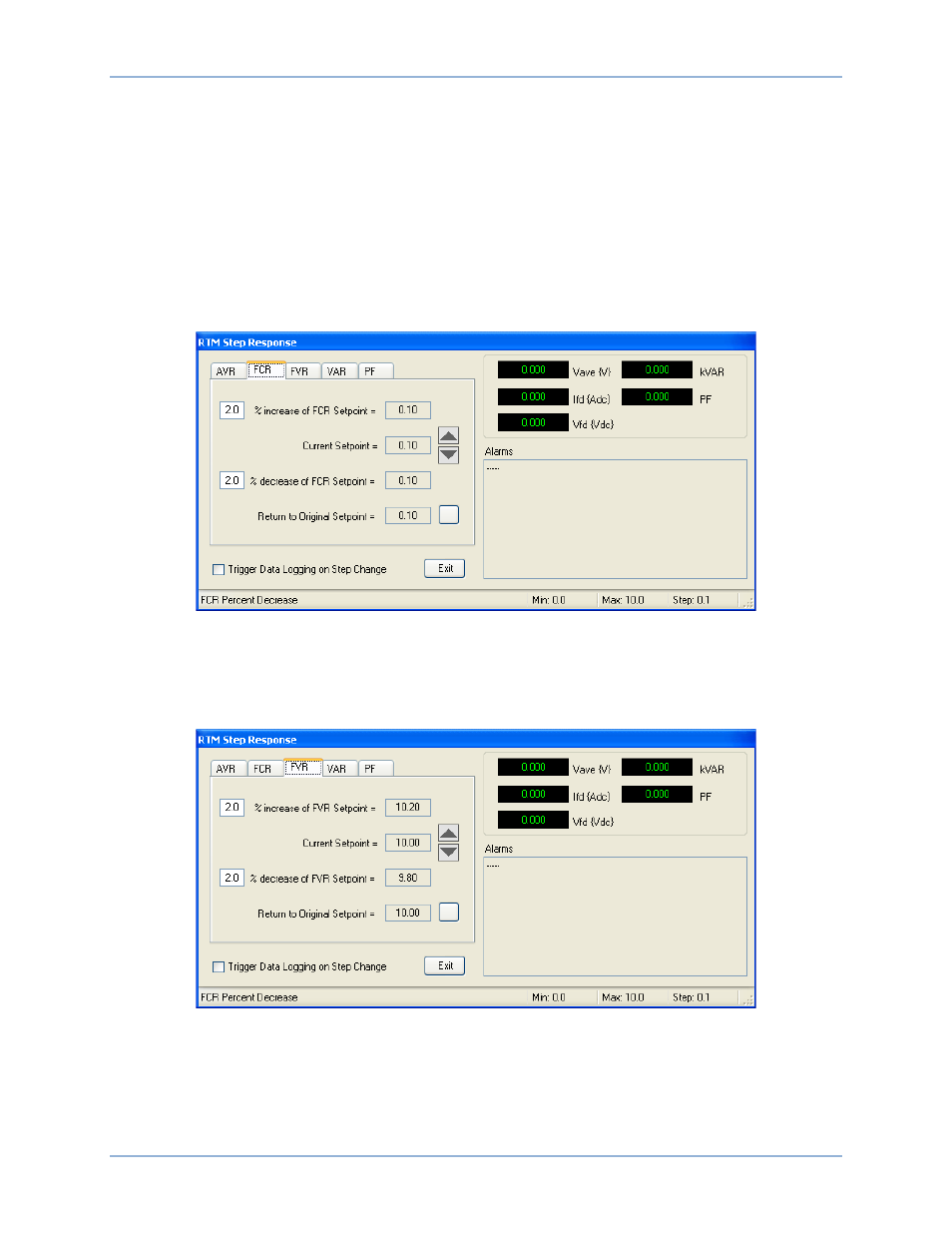
FCR tab functions are shown in Figure 83 and described in the following paragraphs.
The FCR tab of the RTM Step Response screen enables step changes to be applied to the FCR setpoint.
Step changes that increase or decrease the FCR setpoint can be applied by clicking the increment (up
arrow) or decrement (down arrow) button. Step-change setting fields (one for increase and one for
decrease) establish the percent change in the FCR setpoint that occurs when the increment or decrement
button is clicked. A setting of 0 to 10% may be entered in 0.1% increments. Read-only setpoint field
indicate the current setpoint and what the setpoint will be when a step change occurs. A button is
provided to return the FCR setpoint to its original value before any step changes were invoked. This
original value is the FCR setpoint entered on the AVR/FCR/FVR tab of the BESTCOMS Settings screen
and is displayed in the read-only field adjacent to the button.
Figure 83. RTM Step Response Screen, FCR Tab
A checkbox enables the triggering of a data log when a step change is initiated.
FVR Tab
FVR tab functions are shown in Figure 84 and described in the following paragraphs.
Figure 84. RTM Step Response Screen, FVR Tab
The FVR tab of the RTM Step Response screen enables step changes to be applied to the FVR setpoint.
Step changes that increase or decrease the FVR setpoint can be applied by clicking the increment (up
arrow) or decrement (down arrow) button. Step-change setting fields (one for increase and one for
decrease) establish the percent change in the FVR setpoint that occurs when the increment or decrement
button is clicked. A setting of 0 to 10% may be entered in 0.1% increments. Read-only setpoint fields
indicate the current setpoint and what the setpoint will be when a step change occurs. A button is
BESTCOMS™ Software
DECS-400