Basler Electric DECS-400 User Manual
Page 203
9369700990 Rev R
191
4.
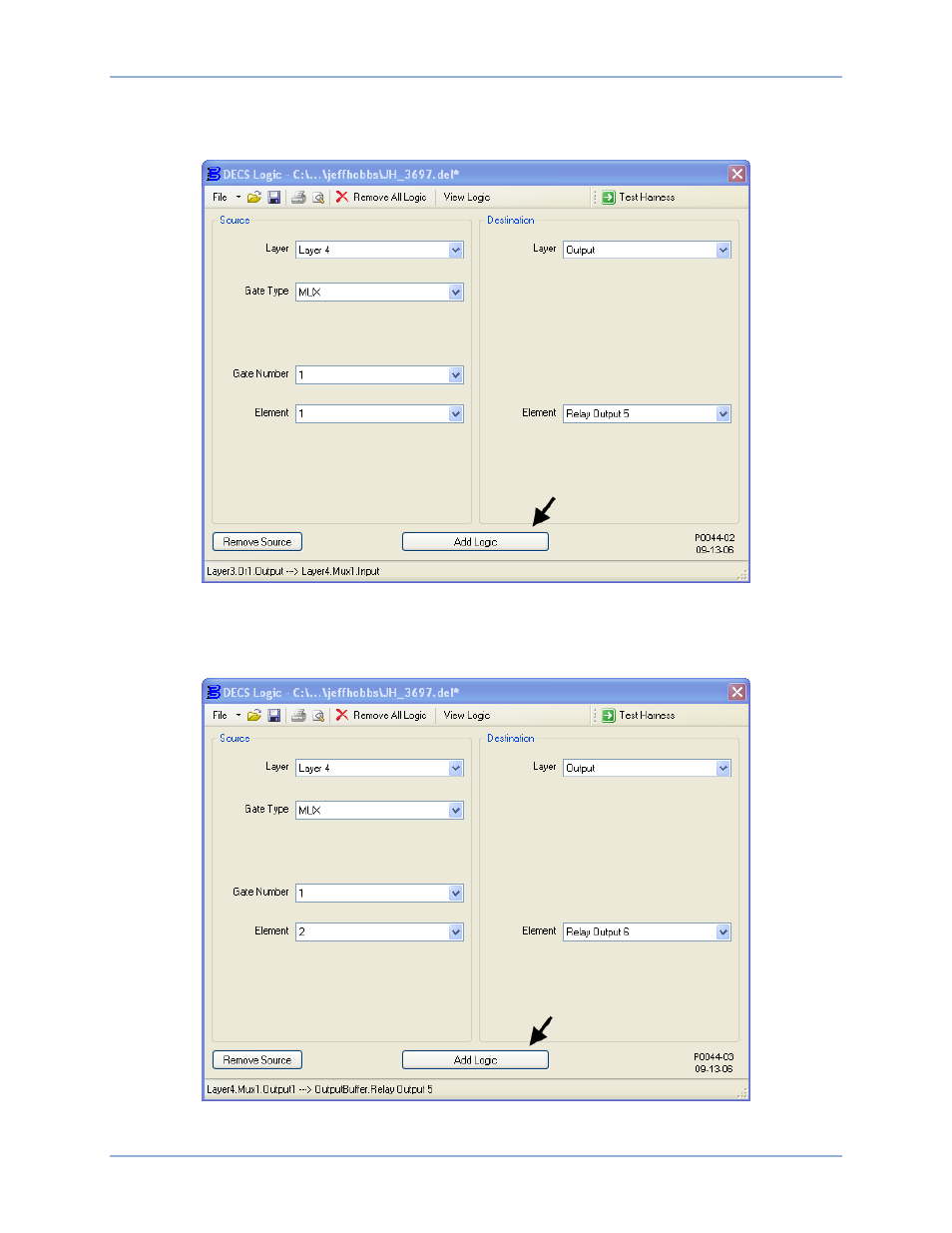
Figure 127 illustrates the DECS Logic window settings associated with this step. Connect output1 of
multiplexer 1 on layer 4 to the Output Relay #5 output buffer. In Table 24, this association is identified
by “DESTINATION: OutputBuffer – Layer4.Mux1.Output1
Relay Output5”.
Figure 127. Addition of OutputBuffer – Layer4.Mux1.Output1 ---> Relay Output5
5.
Figure A-24 illustrates the DECS Logic window settings associated with this step. Connect output 2 of
multiplexer 1 on layer 4 to the Output Relay #6 output buffer. In Table A-2, this association is
identified by “DESTINATION: OutputBuffer – Layer4.Mux1.Output2
Relay Output6”.
Figure 128. Addition of OutputBuffer – Layer4.Mux1.Output2 ---> Relay Output6
DECS-400
Programmable Logic