Cross-current compensation – Basler Electric DECS-400 User Manual
Page 144
132
9369700990 Rev R
Table 18. Field Current Sensing Terminals
Terminal
Description
SH+
Connects to positive output terminal of current shunt
–50
Connects to negative output terminal of 50 mVdc current
shunt (if used)
–100
Connects to negative output terminal of 100 mVdc current
shunt (if used)
Field Voltage Sensing
The field voltage sensing input accepts field voltage at one of five nominal levels. Terminal sets are
provided for a nominal field voltage of 63, 125, 250, 375, and 625 Vdc. Each voltage input has a positive
and negative terminal.
Signal Port
Signal port connector J1 receives operating power from the DECS-400 and sends field current and field
voltage signals to the DECS-400. J1 connects to DECS-400 connector P1 through a cable (Basler P/N
9322900006) supplied with the DECS-400.
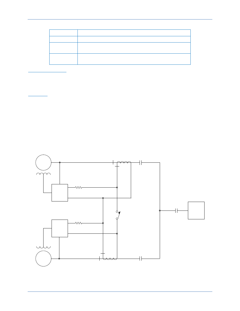
Cross-Current Compensation
Cross-current compensation (reactive differential) mode allows two or more paralleled generators to
share a common load. Figure 93 illustrates a typical cross-current compensation scheme for two
paralleled generators. Each generator is controlled by a DECS-400 using the cross-current compensation
input (CCCT) to sense generator current. The resistors shown in Table 12 are used to set the burden.
Their value may be adjusted to suit the application. Ensure that the power rating of the resistors is
adequate for the installation.
Figure 93. Connections for Cross-Current (Reactive Differential) Compensation
GEN 1
GEN 2
A7
A8
DECS-400
A7
A8
2.0
2.0
CT
CT
LOAD
CCC
ENABLE
CONTACT
09-28-04
P0025-20
DECS-400
Installation
DECS-400